
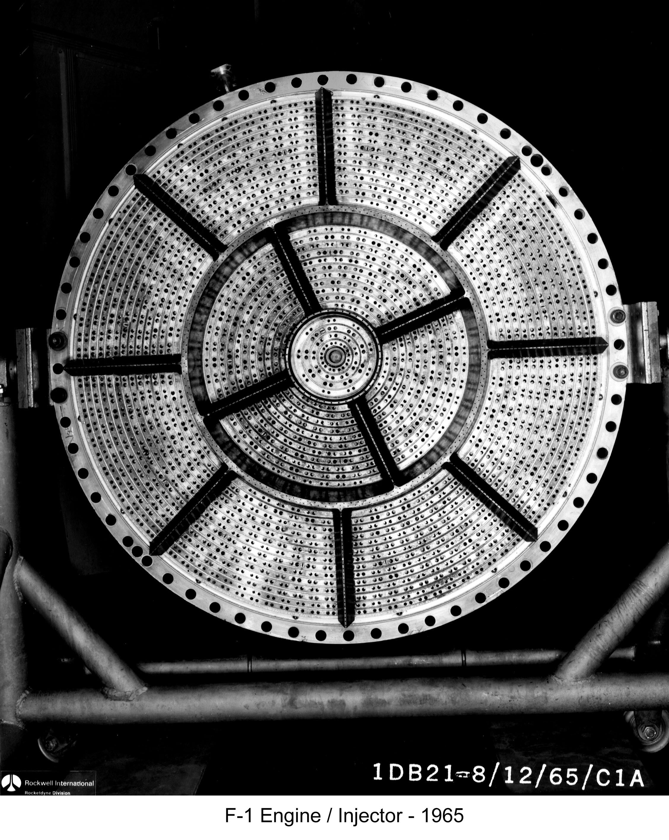
F-1 Engine Injector
Much has been written about the voracious appetite of the Saturn V's S-IC (first) stage engines: They could consume the propellant equivalent of a backyard swimming pool in 10 seconds. They could empty an Olympic-size swimming pool in about 2 ½ minutes. The liquid oxygen (LOX) alone is equivalent to 54 railroad tank cars. Buzz Aldrin once calculated that the S-IC gets about one foot per gallon (although according to heroicrelics calculations, it's closer to 0.6 to 0.7 feet per gallon).
This huge quantity of propellant is pumped from the S-IC's tanks into each F-1 engine's combustion chamber through an injector (sometimes called an injector plate).
Click image for a 2256x2833 pixel version of this image in a new window.
Photo courtesy Vince
Wheelock.
Cleanup by heroicrelics.
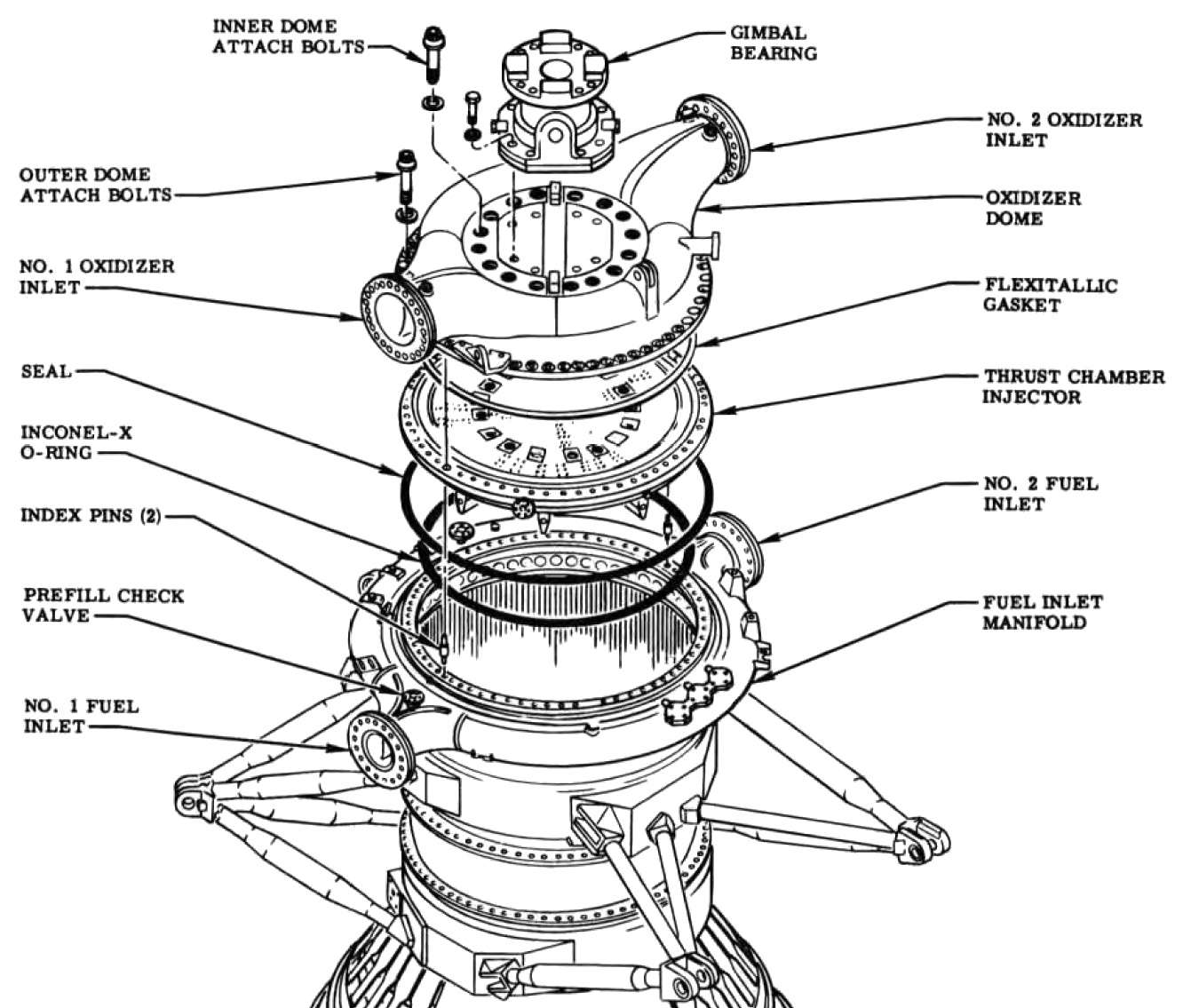
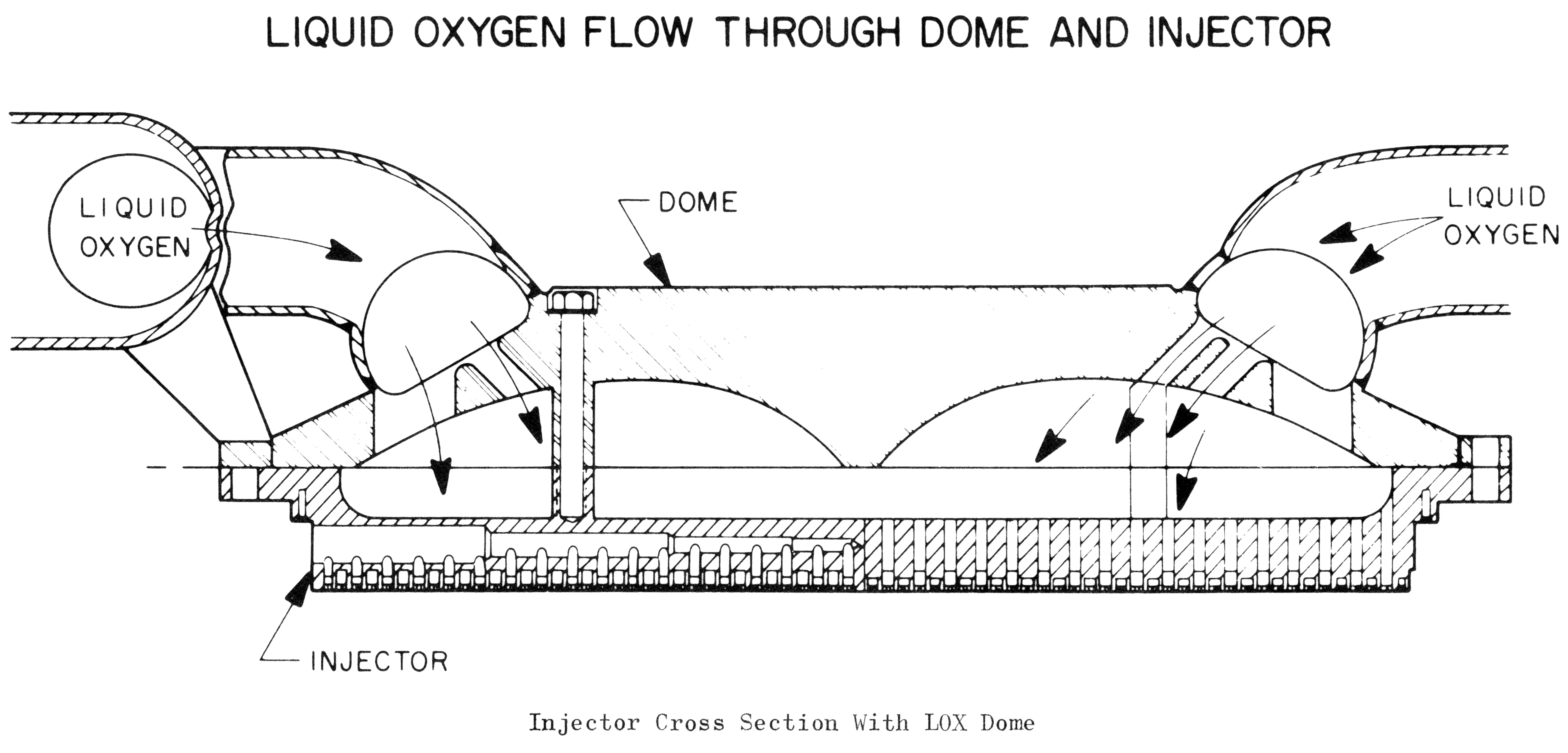
The injector is located near the forward end of the engine. Just forward of the injector is the LOX dome (also called the oxidizer dome), through which the liquid oxygen is directed en route to the injector. The LOX dome is bolted to the injector by 16 inner-dome support bolts, and both the oxidizer dome and the injector are bolted to the thrust chamber body by 64 outer-dome attach bolts. The LOX dome, injector, and thrust chamber body are indexed to each other by means of two noninterchangeable index pins, one diamond-shaped and one round, spaced 180 degrees apart at the interface flanges below the two oxidizer dome inlets. The pins have different diameters; I believe that the diamond-shaped pin has the larger diameter.
Click image for a 1332x1135 pixel version of this image in a new window.
From page 1-7 of the F-1 Engine Familiarization Training Manual,
located in the archives of the U.S.
Space & Rocket Center. A superset of this document is also available
from archive.org.
Extraction and cleanup by heroicrelics.org.
Note the index pin in the exploded-view diagram above. The 64 outer-dome attach bolts and the two holes for the index pins (at the 2:00 and 8:00 positions) are visible in the injector photo at the top of the page.
The following cut-away diagram illustrates liquid oxygen flow from the LOX dome to the injector via holes drilled through the injector. Also note the the outer- and inner-dome attach bolts:
Click image for a 5526x2651 pixel version of this image in a new window.
From Saturn V Booster - The F-1 Engine by D.E. Aldrich. Located
in the Saturn V Collection, Dept.
of Archives/Special Collections, M. Louis Salmon Library, University of
Alabama in Huntsville.
Scan and cleanup by heroicrelics.
The injector's purpose is to distribute the propellants into the combustion chamber at the proper mixture ratio, pressure, and spray pattern to initiate and sustain stable combustion. Determining the "proper mixture ratio, pressure, and spray pattern to initiate and sustain stable combustion" was no easy feat: There were approximately 3200 full-scale tests performed during the development of the F-1 engine, about 2000 of which were conducted during Project First, the F-1 combustion stability program. Since a rocket engine is basically a controlled explosion, it's important to produce combustion which is "dynamically stable"; that is, has predictable combustion which will not create hot spots (and thereby melt the interior of the engine) or burn so rough as to tear the engine apart.
Part of the difficulty in designing an injector with dynamic stability was the sheer size of the F-1 rocket engine: The most powerful rocket engine at the time was the early revision of H-1, with its 165,000 pounds of thrust. The F-1 was to have 1,500,000 pounds of thrust. The F-1 injector had to have what was described as an "extraordinarily high injection density," approximately 5 pounds of propellant per square inch per second. Atlas engines, by comparison, had an injection density of 1.5 lb/in2-sec, and the Apollo Lunar Module Ascent Propulsion System engine and Descent Propulsion System engine were on the order of 0.5 lb/in2-sec.
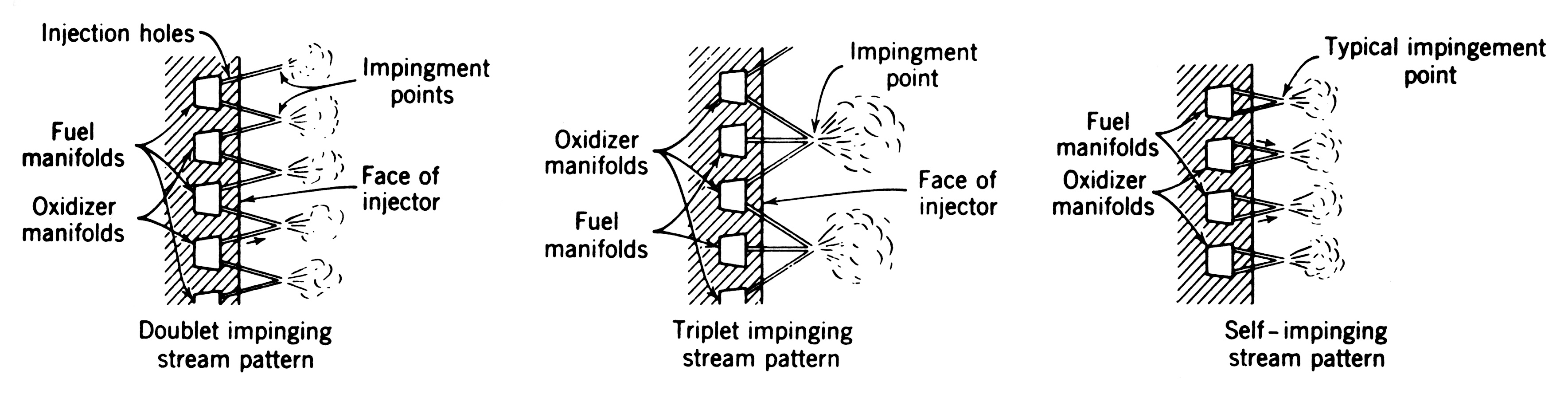
Project First determined the optimal manner in which to inject the propellants into the combustion chamber: The injector face is comprised of 15 rings of oxidizer holes (or orifices) and 14 rings of fuel orifices. The injector face has 1428 oxidizer orifices and 1404 fuel orifices (for a total of 2832 total orifices). The orifices are arranged in pairs such that the propellant being expelled through the holes intersect or impinge in a doublet, like-on-like pattern (i.e., two streams of oxidizer impinge and two streams of fuel impinge). The impinging jets atomize, the fuel and oxidizer vapors intermix, the mixed vapors react (combust), and the resulting hot gases flow out of the combustion chamber to produce thrust. Other impingement patterns tested (and rejected) include a triplet impingement pattern (where three streams intersect) and like-on-unlike (where fuel and oxidizer impinge).
The following diagram, depicting a generic injector (i.e., not the actual F-1 injector), illustrates doublet and triplet impingement patterns (albeit like-on-unlike), as well as a typical like-on-like or self-impinging pattern:
Click image for a 3538x888 pixel version of this image in a new window.
Adapted from p. 299 of Rocket
Propulsion Elements, 6th Edition.
Scan and adaptation by heroicrelics.org.
Early in the F-1 engine's lifecycle, it became clear that a family of injector designs called the "5U" injector showed the most promise. The final injector design (photo above) was a member of the 5U family. Among the 5U variations was the following injector design, which I believe was (or was very similar to) the injector used during the Preliminary Flight Rating Test (PFRT), the injector configuration for which was selected in June 1963. The most visible difference between the following injector and the final injector design is that here the LOX orifices are arranged in triplets, rather than doublets:
Click image for a 2458x1977 pixel version of this image in a new window.
Photo from a review copy of the Historic American Engineering Record's document
regarding Marshall Space
Flight Center, F-1 Engine Static Test Stand (click the "data pages" link),
courtesy Alan Lawrie.
Extraction and clean-up by heroicrelics.
Project First also determined that the most stable combustion could be achieved by varying both the angle of impingement and the diameter of the orifices (the latter of which controlled the velocity of the injected propellant), depending upon the location on the injector face. The following diagram identifies the number and size of orifices on the final F-1 injector design:
Click image for a 1589x2491 pixel version of this image in a new window.
From p. 673 (p. 17 in the PDF) of "Comprehensive
Review of Liquid-Propellant Combustion Instabilities in F-1 Engines"
[direct link to 3.8M PDF).
Extraction and adaptation by heroicrelics.org.
Another injector feature important to promoting stable combustion was the use of baffles on the injector face. Baffles alter the acoustic resonance characteristics of the combustion chamber, dampening tangential and transverse combustion instability shock waves generated during combustion.
For the F-1, 15 different baffle configurations were tested. In the final configuration, two circular and 12 radial baffles divided the injector face into 13 compartments. These compartments are identified numerically, 1 through 13, and the baffles are identified alphabetically, A through N. The 12 radial, fuel-cooled, copper baffles are supplied with fuel by the outer circular baffle to which they are brazed. The center of compartment No. 13 is threaded for the attachment of the throat plug shaft.
From page 1-9A of the F-1 Engine Familiarization Training Manual,
located in the archives of the U.S.
Space & Rocket Center. A superset of this document is also available
from archive.org.
Extraction, adaptation, and cleanup by heroicrelics.
Cleanup and adaptation by heroicrelics.
The injector measured about 44 inches in diameter, with about 39 inches of that exposed to the combustion chamber. The injector was about 8 inches thick, from back to injector face. It had a CRES (corrosion-resistant steel; more commonly known outside the aerospace industry as stainless steel) body with 31 ring grooves, 16 fuel ring grooves alternating with 15 oxidizer ring grooves. The fourteen copper rings containing the fuel orifices and the 2 circular copper baffles were brazed to the fuel ring grooves. The fifteen copper rings containing the oxidizer orifices were brazed to the oxidizer ring grooves.
As detailed above, the oxidizer ring grooves were supplied with oxidizer from the LOX dome by axially drilled holes. The fuel ring grooves were supplied from the fuel inlet manifold (shown in the exploded view diagram above) by 32 radial fuel feed passages. The arrangement of fuel feed passages in a typical injector is depicted in the following diagram:
Click image for a 1326x1611 pixel version of this image in a new window.
Adapted from pp. 124 and 125 (p. 133 & 134 in the PDF) of Design of Liquid
Propellant Rocket Engines, Second Edition.
Extraction, cleanup, and adaptation by heroicrelics.org.
The following cut-away diagram of a typical rocket engine combustion chamber depicts an injector's ring grooves and orificed copper rings, with the ring grooves fed by fuel feed passages and holes from the LOX dome:
Click image for a 1879x1722 pixel version of this image in a new window.
Adapted from page 7 (p. 16 in the PDF) of Liquid Rocket
Engine Injectors.
Extraction, cleanup, and adaptation by heroicrelics.org.
The fuel feed passages on an F-1 injector are visible in this view of the injector from the Marshall Space Flight Center F-1 disassembly project back in 2012. The injector is mounted on a handling fixture and the ends of several fuel feed passages are visible.

Click image for more information about this picture; opens in a new window.
Picture by heroicrelics.org.
The following cut-away diagram of the F-1 injector shows the axially-drilled holes supplying LOX to the oxidizer groove rings and a fuel feed passage supplying RP-1 to the fuel ring grooves. It also shows the flow of fuel used to cool the circular and radial baffles.
Click image for a 2658x691 pixel version of this image in a new window.
Adapted from p. 1-2 of the F-1 Rocket Engine
Technical Manual Supplement (R-3896-1A)
Adaptation by heroicrelics.
In addition to its duties in sustaining proper combustion, the injector also played a role in the initial ignition of the engine.
The F-1's propellants, RP-1 and LOX, require an external ignition source to initiate combustion. For the F-1, this was provided by the hypergol manifold assembly. Attached to a bracket on the thrust chamber fuel manifold, the hypergol manifold assembly included a cartridge containing a fluid consisting of 85 percent triethylborane and 15 percent triethylaluminum. These two compounds are pyrophoric, meaning that they will ignite spontaneously in the presence of oxygen. During the engine ignition sequence, this fluid was released through 25 igniter fuel orifices on the injector (two igniter fuel housings in each of the 12 outer compartments and one igniter fuel housing in the center compartment) where it spontaneously combusted with the LOX already in the combustion chamber, establishing ignition.
The photo below shows several of the igniter fuel housings, which look much like the heads of slotted screws, on the face of the injector:

Click image for more information about this picture; opens in a new window.
Picture by heroicrelics.org.
Most of the information presented above is summed up in this cut-away diagram of the F-1 injector:
Click image for a 1428x1119 pixel version of this image in a new window.
Photo courtesy Vince
Wheelock.
Cleanup by heroicrelics.
"View A" in the upper left of the diagram shows how fuel entered the injector from the fuel inlet manifold. Every other tube comprising the thrust chamber was a "down tube", and is slotted on its outboard side at the fuel inlet manifold area. A bypass orifice plug was brazed into the tube above this slot to permit 30% of the fuel to go directly to the fuel injector manifold. The remaining 70% of the fuel was used for regenerative cooling of the thrust chamber, being directed down the tube to the fuel return manifold at the end of the thrust chamber. From the fuel return manifold, the fuel is directed by the adjacent fuel return tubes to the fuel injector manifold. From the fuel injector manifold, the fuel enters the fuel feed passages.
Of special note is the hypergol manifold in View A in the upper left of the diagram. Feed lines inside the fuel feed passages deliver the pyrophoric fluid from this manifold to the igniter fuel housings (several of fuel feed passages have hypergol feed lines in the injector edge photo, above):
Detail of the injector end cut-away.
Cleanup and adaptation by heroicrelics.
The diagram also shows how the outer circular baffle feeds both the inner and outer radial baffles:

Detail of the Injector cut-away.
Cleanup and adaptation by heroicrelics.
For additional information regarding the injector baffles, see my F-1 injector baffle page.
References
The NASA Technical Reports Server (NTRS) once served a number of documents (albeit not a complete set) containing additional information on Project First, the F-1 engine combustion stability program:
- History: Project First, F-1 Combustion Stability Program, Volume 1, Book 1 [direct link to 3.1M PDF]
- History: Project First, F-1 Combustion Stability Program, Volume 2, Book 3 [direct link to 5.4M PDF]
- History: Project First, F-1 Combustion Stability Program, Volume 2, Book 4 [direct link to 5.5M PDF]
- History: Project First, F-1 Combustion Stability Program, Volume 3, Book 1 [direct link to 4.9M PDF]
- History: Project First, F-1 Combustion Stability Program, Volume 3, Book 2 [direct link to 8.8M PDF]
In researching this page, I drew information (including a number of verbatim text passages) from the following sources: