
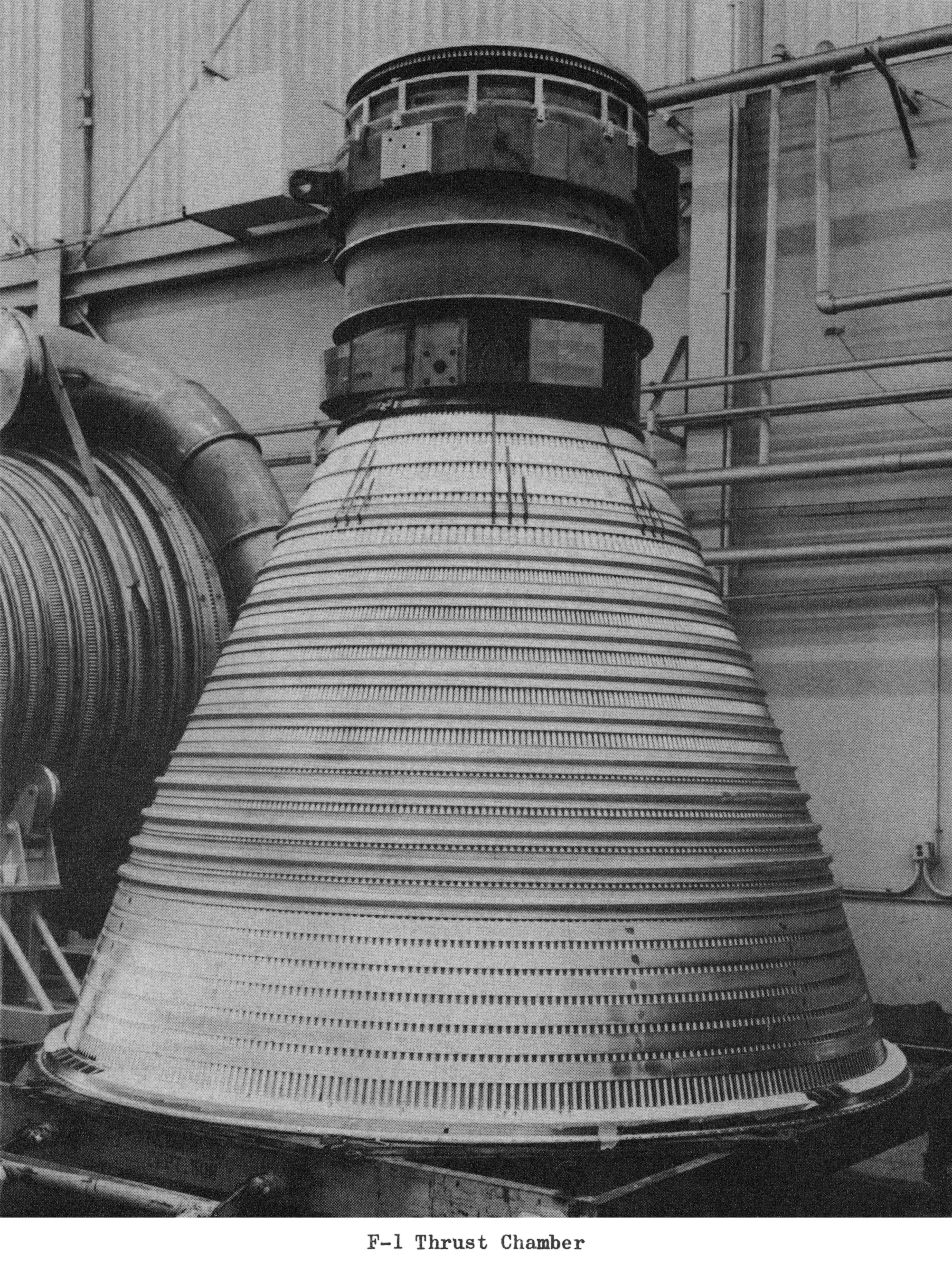
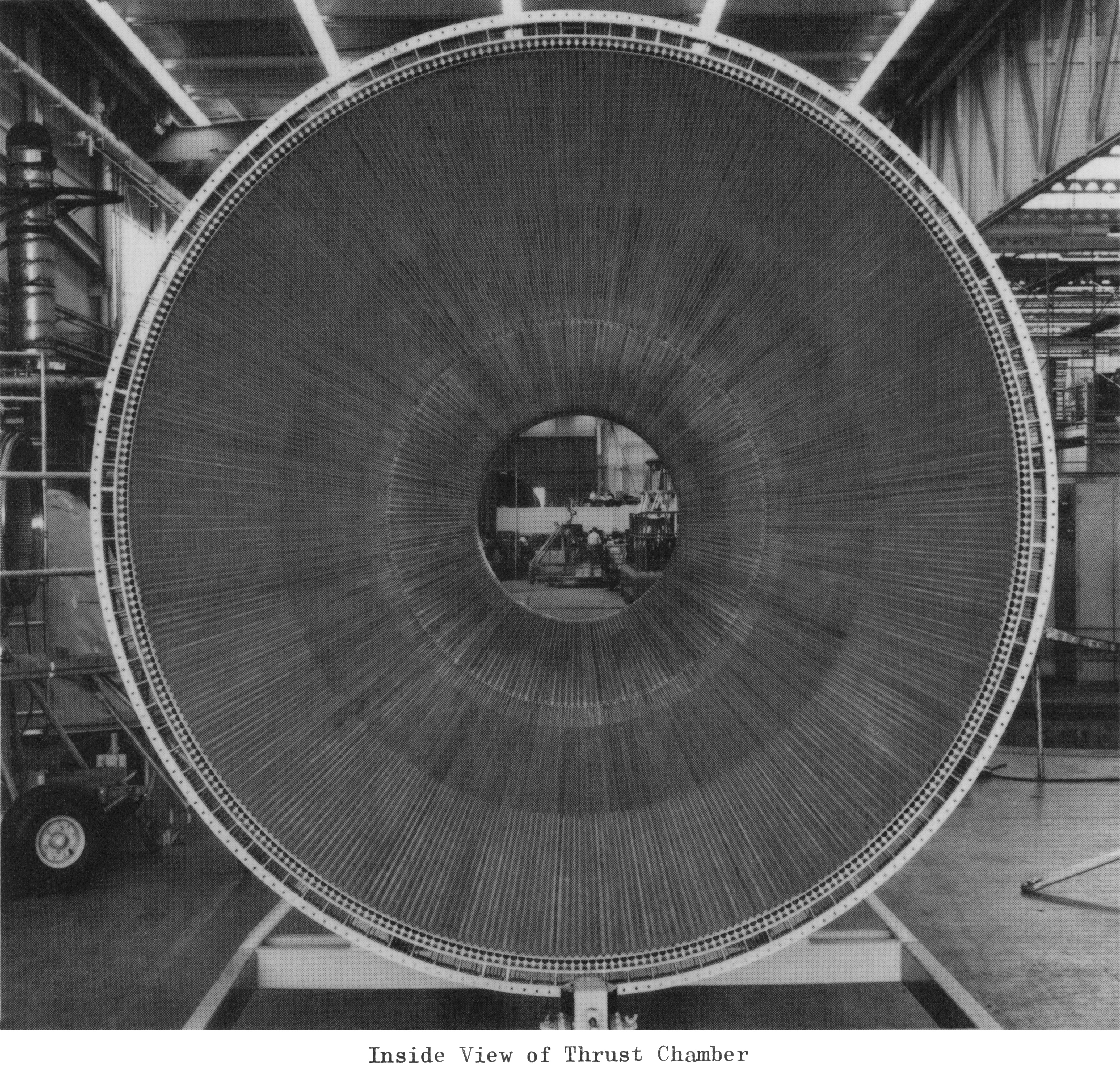
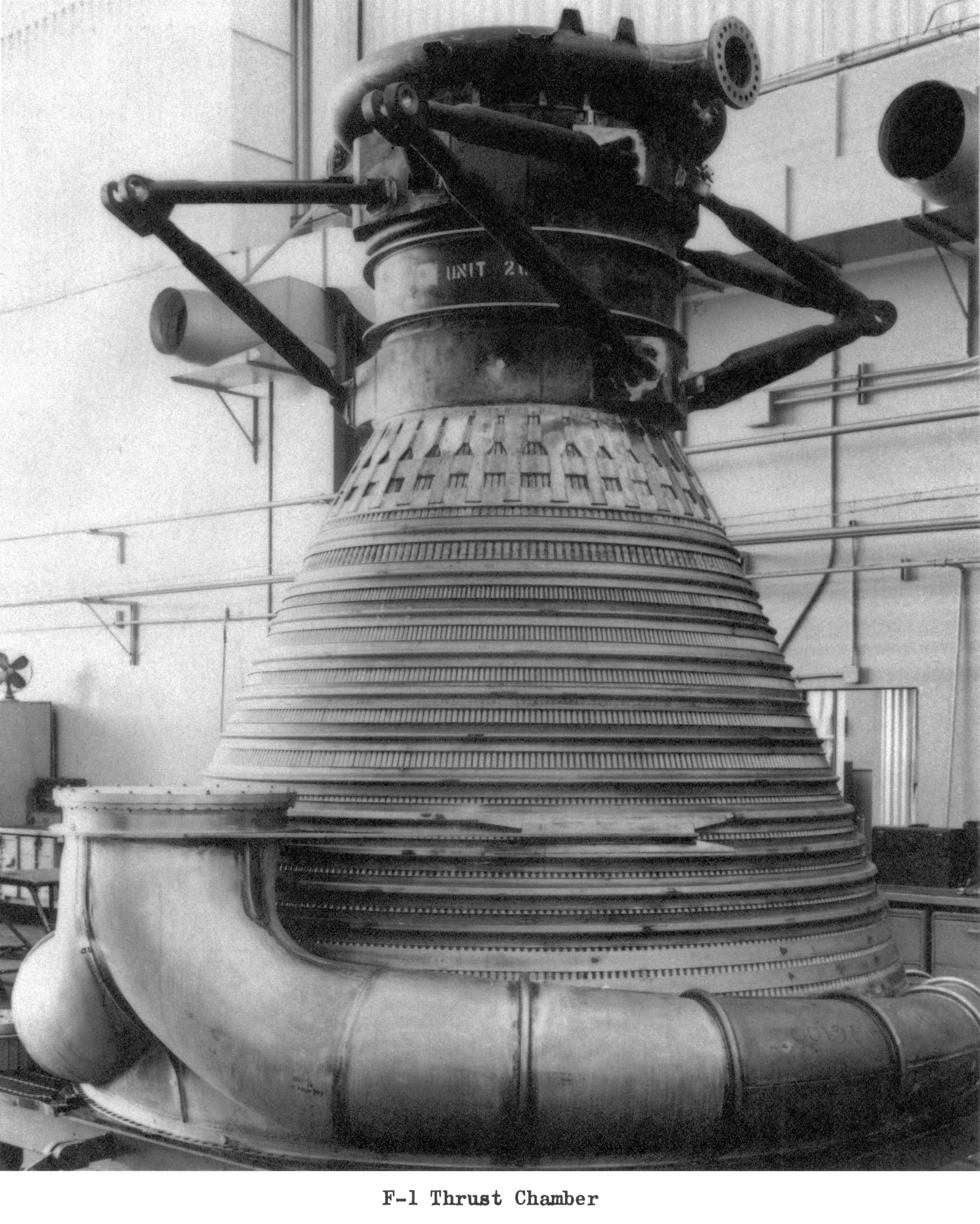
F-1 Thrust Chamber
The thrust chamber is the most recognizable portion of the F-1 rocket engine. While the entire thrust chamber assembly consists of a gimbal bearing, an oxidizer dome, an injector, a thrust chamber body, a thrust chamber nozzle extension, and thermal insulation, this page will deal with the thrust chamber itself. This page will additionally refer to the thrust chamber body, without its nozzle extension, unless otherwise specified.
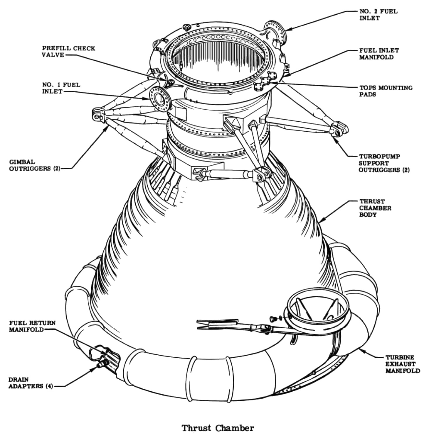
Propellants were delivered to the thrust chamber from the turbopump via the high-pressure ducts. The thrust chamber provided a combustion chamber for burning propellants and an expansion nozzle for expelling gasses produced by the burned propellants at high velocity to produce thrust. The thrust chamber was tubular-walled and regeneratively fuel-cooled to the 10:1 expansion ratio plane. The nozzle was bell-shaped and, with its uncooled nozzle extension, had an overall expansion ratio of 16:1. There were four sets of outrigger struts attached to the exterior of the thrust chamber: two sets of the struts were turbopump mounts and the other two were attach points for the gimbal actuators. The thrust chamber incorporated a turbine exhaust manifold at the nozzle exit and a fuel inlet manifold at the injector end which directed fuel to the fuel down tubes. Brackets and studs welded to the reinforcing "hatbands" surrounding the thrust chamber provided attach points for thermal insulation blankets.
Click image for a 1461x1501 pixel version of this image in a new window.
Adapted from page 1-7 of the F-1 Engine Familiarization Training
Manual, located in the archives of the U.S.
Space & Rocket Center. A superset of this document is also available
from archive.org.
Extraction, adaptation, and cleanup by heroicrelics.
The thrust chamber was approximately 11 feet in length and 9-1/2 feet in diameter at the aft end of the nozzle. Its body was constructed of tubes; fuel flowed through these tubes, providing regenerative cooling to prevent the tube material from melting during engine operation.
The fuel entered the fuel inlet manifold at the forward end of the thrust chamber, where it was directed to the regenerative cooling tubes. Every other tube comprising the thrust chamber was a "down tube". Fuel was admitted to each down tube via a slot on its outboard side at the fuel inlet manifold area; a bypass orifice plug brazed into the tube above this slot permitted 30% of the fuel to be admitted directly to the fuel injector manifold. The remaining 70% of the fuel was directed down the tube for regenerative cooling of the thrust chamber.
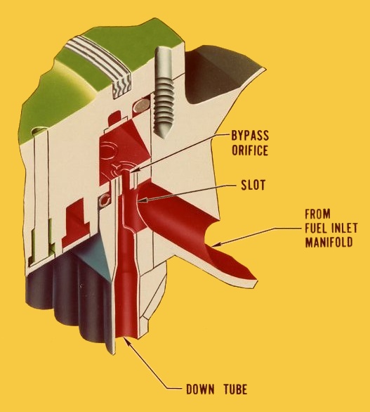
Adapted from my F-1 Injector End
Cut-Away diagram.
Cleanup and adaptation by heroicrelics.
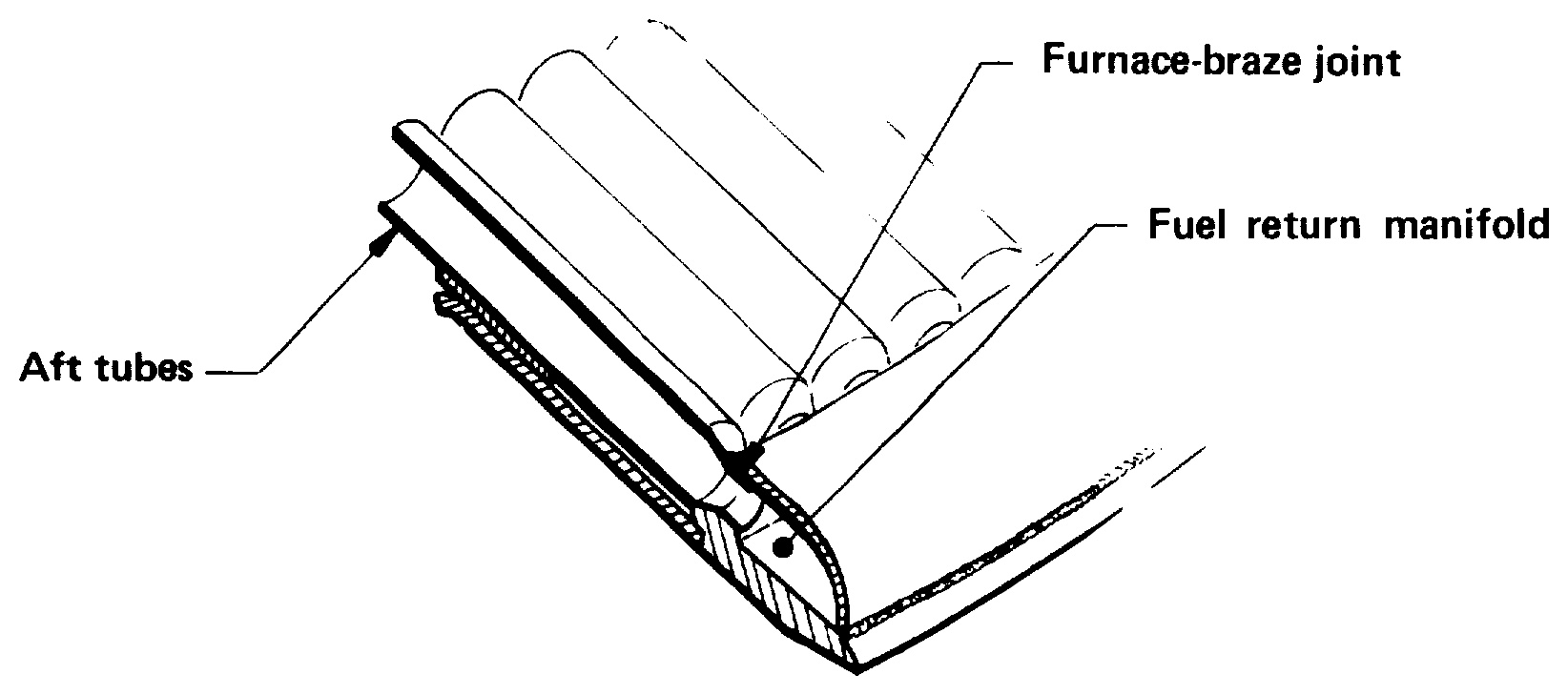
At the exit plane of the thrust chamber was a fuel return manifold; fuel was directed back up the adjacent fuel return tubes to the fuel injector manifold at the forward end of the thrust chamber.

Click image for a 1285x1186 pixel version of this image in a new window.
From "F-1 Engine Development" by D.E. Aldrich and D.J. Sanchini on
page 46 of the the March 1961 issue of Astronautics. Located in
the Saturn V Collection, Dept. of
Archives/Special Collections, M. Louis Salmon Library, University of
Alabama in Huntsville.
Scan and cleanup by heroicrelics.
The tubes comprising the thrust chamber were heavily jacketed at the combustion chamber and were reinforced by a series of bands around the nozzle. The thrust chamber's tubes were constructed of Inconel X-750, a high-temperature, heat-treatable, nickel base alloy. 178 primary tubes, hydraulically formed from 1-3/32 inch outside diameter Inconel-X tubing, made up the chamber body above the 3:1 expansion ratio plane (approximately 30 inches below the throat centerline plane). At this point, the tubes bifurcated, or split in two. Two one-inch-outside-diameter secondary tubes were spliced to each primary tube and formed the chamber from the 3:1 to the 10:1 expansion ratio plane.

Detail of the Thrust Chamber and Nozzle
Extension.
Cleanup by heroicrelics.
This bifurcation was necessary due to a combination of geometry and material science. The circumference of a nozzle is at a minimum at the throat and increases in the nozzle expansion section. The amount of increase in circumference which can be obtained with a fixed number of tubes is limited by how much the tubes can be worked by tapering (varying the tube cross section) and forming. When the point at which the circumference cannot be further increased with the fixed number of tubes is reached, a bifurcation joint is necessary.
At moderate expansion ratios (about 8:1), the nickel and stainless steel tubing used on other rocket engines' thrust chambers could be tapered or otherwise formed successfully (e.g., compare the shape of the tubes at the combustion chamber to the shape near the exit plane of the H-1 rocket engine; similar engines include the Jupiter, Thor, and Atlas booster). For larger expansion ratios, however, some method for increasing the number of tubes in the nozzle aft end is required. The J-2 (expansion ratio of 27 ½:1) and the RL10 (expansion ratio of 40:1 in the contemporary variant) employ a pass-and-a-half construction to increase the number of tubes and obviate the need for a splice joint. The Atlas sustainer (expansion ratio of 25:1) increases the number of tubes with a bifurcation joint, at the 7:1 expansion ratio plane.
Inconel X-750 tubing was chosen for the F-1's thrust chamber because it provided the required high strength-to-weight ratios needed to withstand the engine's thrust requirements, which were nearly ten times greater than any previous rocket engine. The high-strength property of this alloy permitted design of thinner wall section tubes, resulting in minimum weight. The thinner tubes also design provided adequate thrust chamber cooling with only approximately two-thirds of the total available fuel flow passing through the tubes. Therefore, the bypass arrangement described above was used to reduce the system pressure drop.
Because Inconel X-750 was a high-nickel alloy, it possessed a low ductility. This material, coupled with the tubes' large diameter, thin walls, high internal operating pressure, and rounded tube crowns made tapering much more difficult, necessitating the bifurcated design. This arrangement also proved to be lighter than using a single tube to the 10:1 expansion ratio plane.
Rectangular splice joints had been used for engines with secondary tube widths of 0.5 inch or less, such as the Atlas sustainer. For the F-1, with its larger tubes, relatively thin walls, high internal operating pressure, and rounded tube crowns, the "D" splice was developed: The ends of the primary tube and the two secondary tubes were shaped as shown, the ends of the secondary tubes were fusion welded together, and the primary and secondary tubes were induction brazed together.

Click image for a 1874x1597 pixel version of this image in a new window.
Adapted from page 57 (p. 73 in the PDF) of Liquid Rocket Engine
Fluid-Cooled Combustion Chambers.
Extraction and adaptation by heroicrelics.
The welds joining the two secondary tubes are able to withstand thrust chamber destruction as spent F-1 engines hit the ocean's surface, as witnessed by this pair of tubes from my Recovered F-1 Engine Conservation photo set:

Click image for more information about this picture; opens in a new window.
Photo by heroicrelics.org.
This subassembly (one primary tube brazed to two secondary tubes) was then used in thrust chamber fabrication. Assembling the tube subassemblies into the jacket and end rings was referred to as the "stacking operation" and was done in a "stacking fixture" which kept alignment between the tube bundle, jacket, and end rings prior to brazing the entire entire bundle into a thrust chamber (brazing is a process in which joining is accomplished by melting a filler metal into closely fitted joints between a number of metal parts).
An early design for the F-1 thrust chamber had a completely regeneratively-cooled nozzle, all the way to the 16:1 expansion plane, which incorporated two bifurcation joints. This concept, however, was altered early on to use the uncooled nozzle extension from the 10:1 to the 16:1 expansion plane. Even with "only" 178 primary and 356 secondary tubes, the F-1 had over 3,000 feet of joints between the tubes to be brazed together.
Here are two photos of the bifurcation joint. The first is of the exterior of the thrust chamber and the second is from the interior:

Click image for more information about this picture; opens in a new window.
Photo by heroicrelics.org.

Click image for more information about this picture; opens in a new window.
Photo by heroicrelics.org.
The brazed joints between the tubes served primarily as a seal to contain the combustion gasses within the chamber. Although the brazed joints provided some resistance to the separating forces generated by the internal gas pressure, the primary load was borne by the jacket and bands surrounding the tube bundle. With the greatly increased power and high thrust-to-weight ratio imposed by the design requirements on the F-1 and the Inconel X-750 tubing, a more sophisticated brazing process than that used with earlier engines had to be developed.
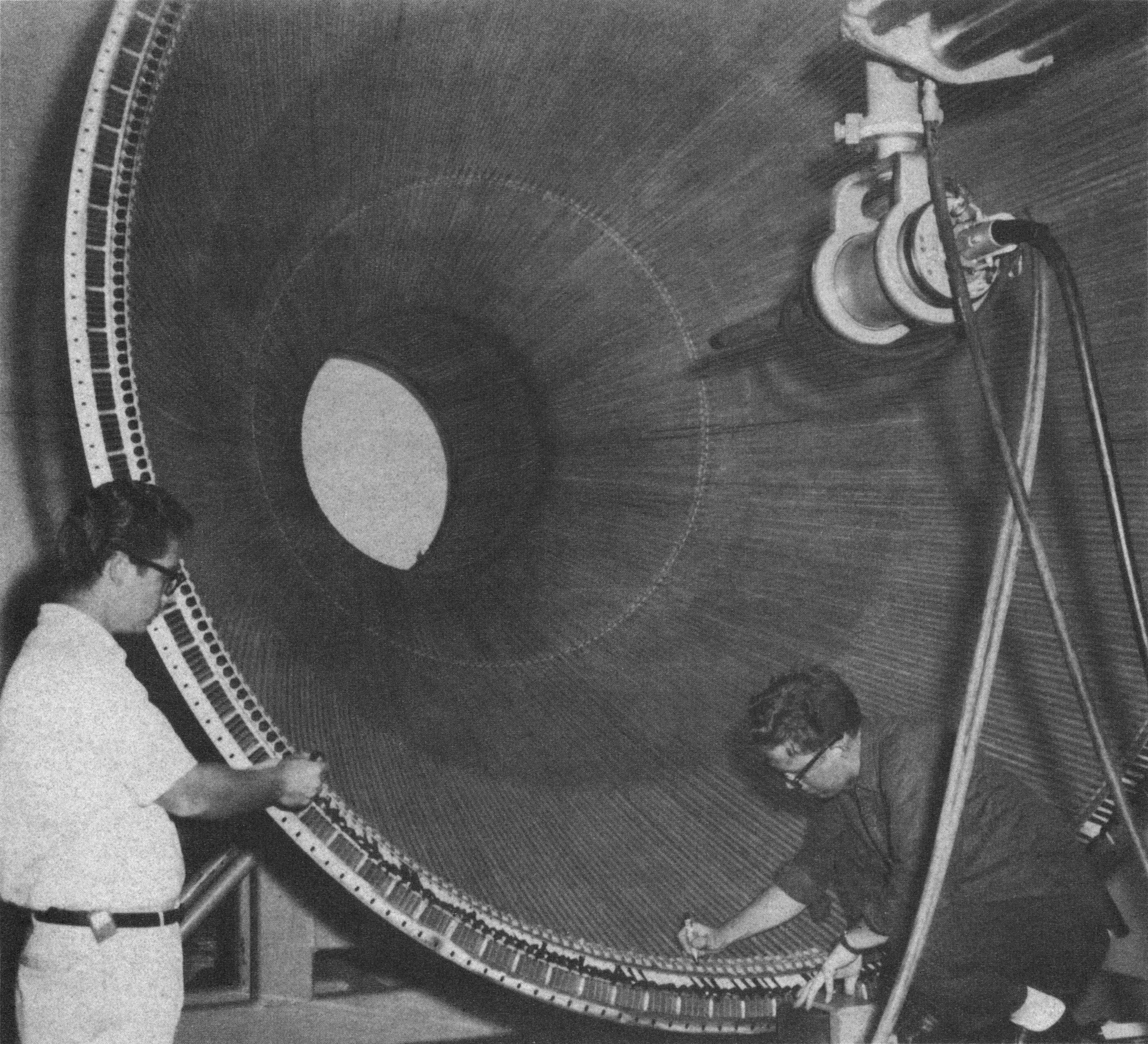
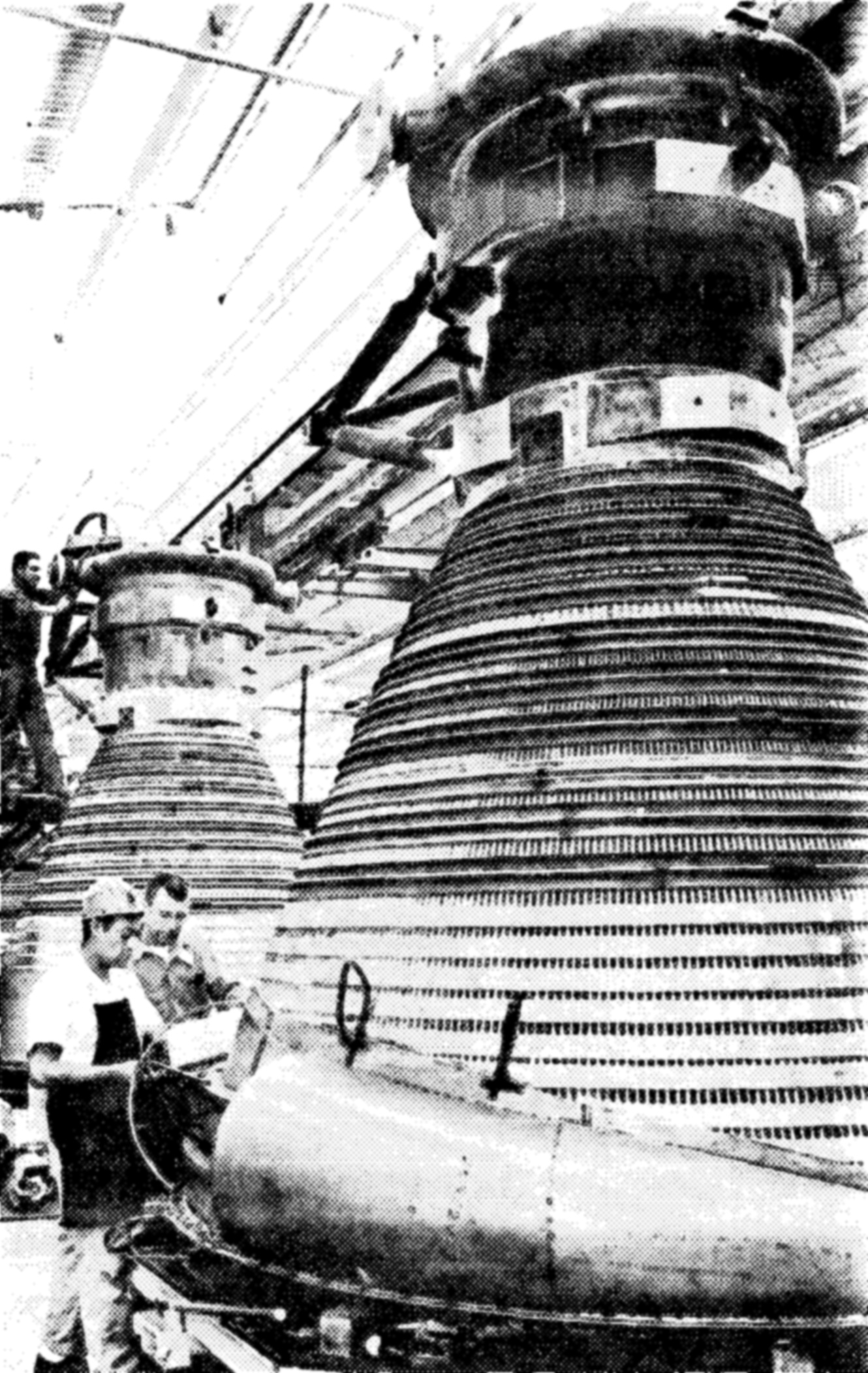
Here are two photos showing F-1 engines early in the fabrication process, with little more than the tubes, bands, and jacket:
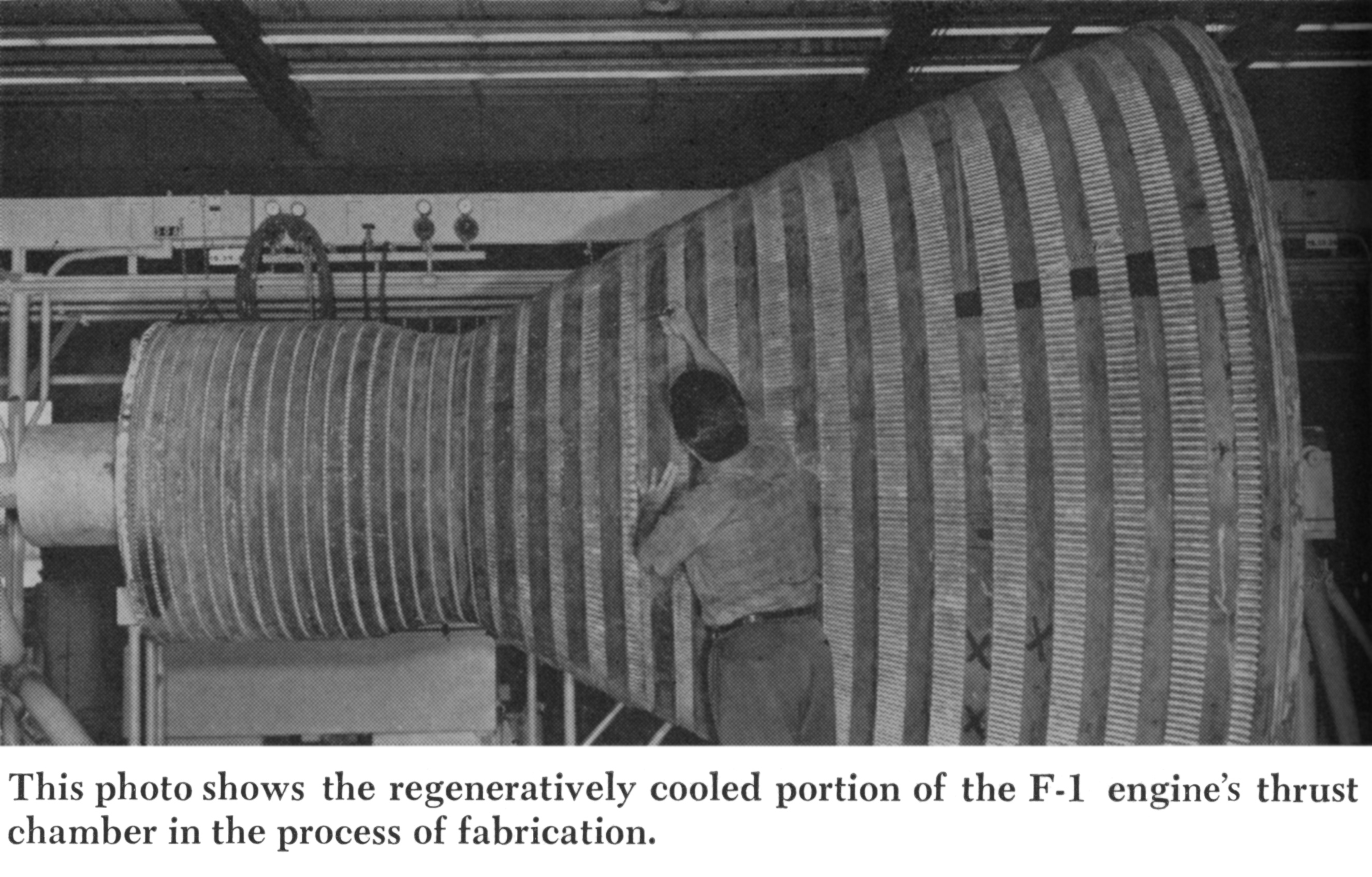
Click image for a 2650x1693 pixel version of this image in a new window.
From "F-1 Engine Development" by D.E. Aldrich and D.J. Sanchini on
page 46 of the the March 1961 issue of Astronautics. Located in
the Saturn V Collection, Dept. of
Archives/Special Collections, M. Louis Salmon Library, University of
Alabama in Huntsville.
Scan and cleanup by heroicrelics.
Click image for a 3909x5197 pixel version of this image in a new window.
From page 4 of "Furnace
Brazing the F-1 Thrust Chamber for Apollo" by Francis X. De Carlo. Located
in the Saturn V Collection, Dept. of
Archives/Special Collections, M. Louis Salmon Library, University of Alabama in
Huntsville.
Scan and cleanup by heroicrelics.
Turning our attention now away from the minutia of metallurgy and manufacturing and back to the features of the F-1 thrust chamber, the No. 1 (fuel-up) tube and Nos. 60 and 120 tubes (both fuel-down) were identified on the chamber internal faces of the injector end ring and fuel return manifold with a raised weld bead with the tube number and a directional flow arrow. These tubes were similarly marked on the thrust chamber's exterior on the reinforcing bands and straps below the engine's throat. See my F-1 engine tube markings page for additional information.
The 70 percent of the fuel used for regenerative cooling flowed through the fuel-down tubes to the fuel return manifold at the end of the thrust chamber. From the fuel return manifold, the fuel was directed up the adjacent fuel return tubes to the fuel injector manifold. The return manifold was welded to the bottom of the thrust chamber secondary tubes and incorporated four drain ports, located 90 degrees apart, to drain residual fluids. Forty lugs were welded to the inside wall of the return manifold for attaching the turbine exhaust leak-test fixture.
Click image for a 1644x729 pixel version of this image in a new window.
Adapted from page 64 (p. 80 in the PDF) of Liquid Rocket Engine
Fluid-Cooled Combustion Chambers.
Extraction, cleanup, and adaptation by heroicrelics.

Detail of the Thrust Chamber and Nozzle
Extension.
Cleanup and adaptation by heroicrelics.
The fuel return manifold was welded to the thrust chamber after its brazing operation. Here are two photos of the thrust chamber prior to mating with the fuel return manifold. The "halo" around the periphery of the thrust chamber exit is part of the turbine exhaust manifold, discussed next.
Click image for a 4123x3751 pixel version of this image in a new window.
From page 32 of Furnace
Brazing the F-1 Thrust Chamber for Apollo" by Francis X. De Carlo. Located
in the Saturn V Collection, Dept. of
Archives/Special Collections, M. Louis Salmon Library, University of Alabama in
Huntsville.
Scan and cleanup by heroicrelics.
Click image for a 4214x4058 pixel version of this image in a new window.
From page 16 of "Saturn V Booster - The F-1 Engine" by D.E. Aldrich.
Located in the Saturn V Collection, Dept. of Archives/Special
Collections, M. Louis Salmon Library, University of Alabama in
Huntsville.
Scan and cleanup by heroicrelics.
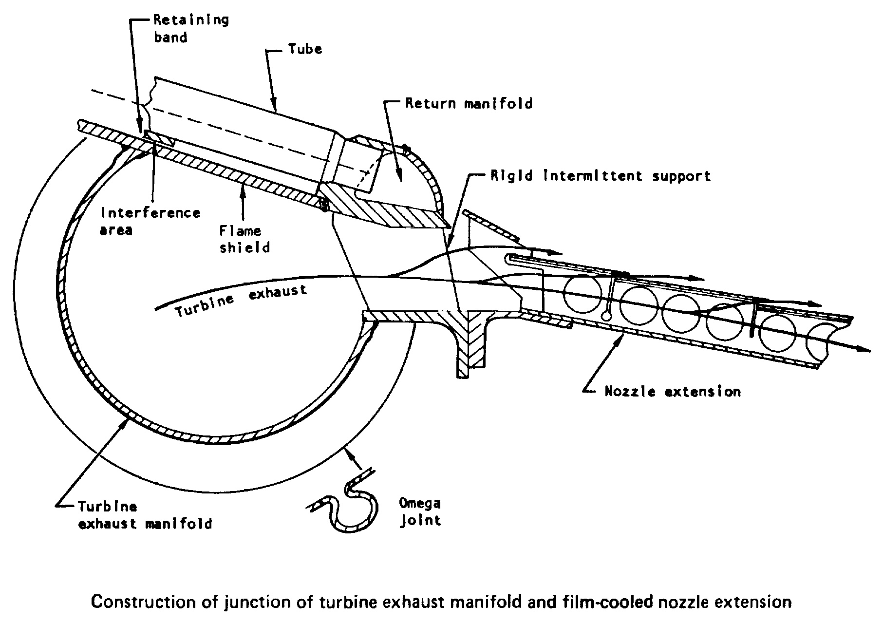
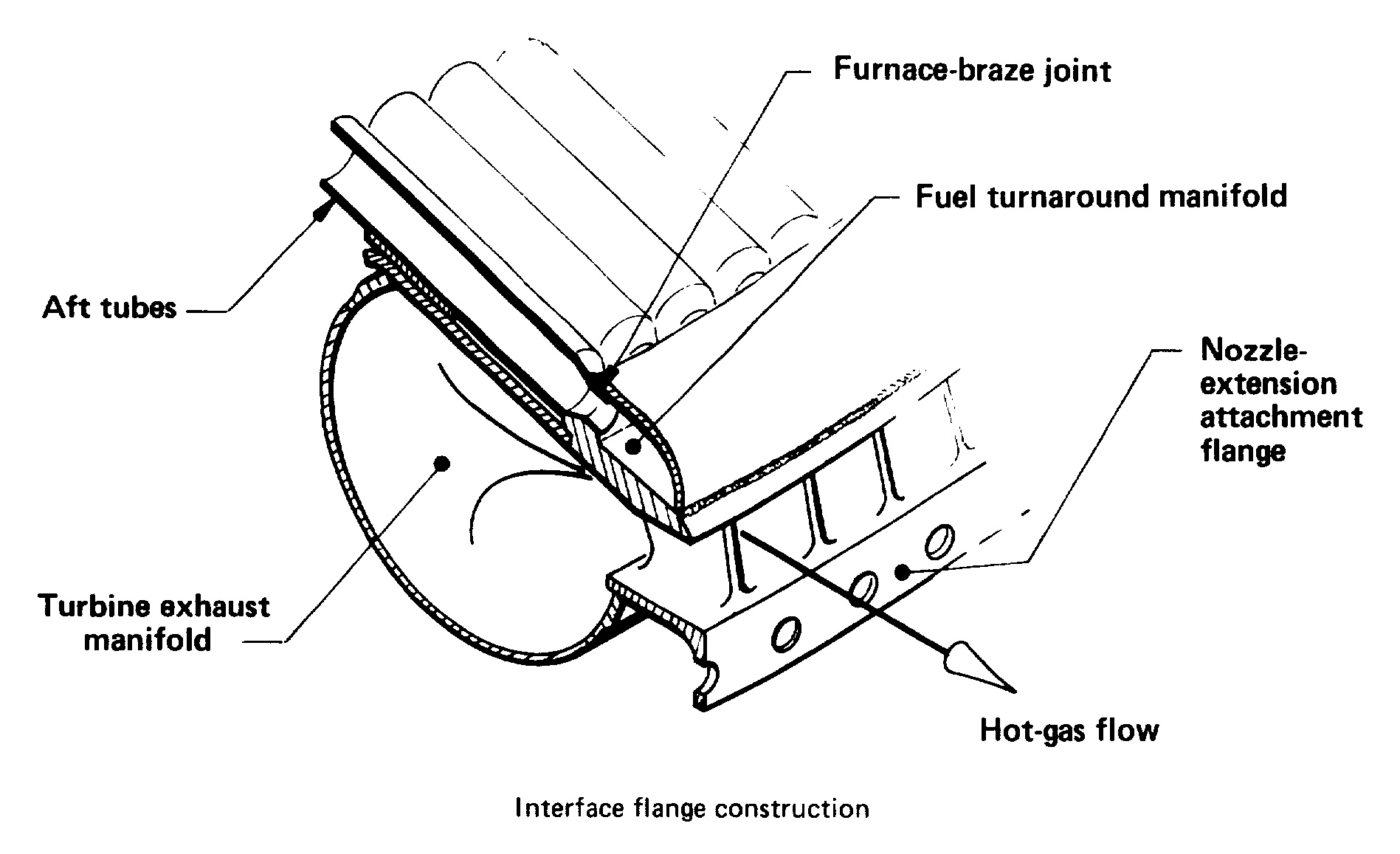
The turbine exhaust gasses, after powering the turbopumps and flowing through the heat exchanger, were routed to the turbine exhaust manifold, which collected and evenly distributed the gasses to the area between the walls of the nozzle extension, where the gas provided film cooling for the inner wall of the nozzle extension. The exhaust manifold, fabricated from preformed CRES (stainless steel) sheets, formed torus of decreasing (from inlet to exit) cross-sectional area incorporating 15 omega expansion joints to compensate for thermal growth. The exhaust manifold was welded to a flame shield which itself was welded to the outer wall of the thrust chamber.
Click image for a 1813x1281 pixel version of this image in a new window.
From page 51 (p. 65 in the PDF) of Liquid Rocket
Engine Nozzles.
Extraction, cleanup, and adaptation by heroicrelics.
Here we see the turbine exhaust manifold being assembled. Note the flame shield between the thrust chamber and the metal sheets comprising the manifold. It seems odd that there are no omega joints in the manifold at this point in the assembly process; due to the added complexity, it seems unlikely that they would be added later, after the metal sheets had been joined to the thrust chamber. Since this photo is dated 1963 (fairly early in the F-1 program), it's possible that this is a pre-production engine and the omega expansion joint was added later due to lessons learned in early testing.
Click image for a 1330x2103 pixel version of this image in a new window.
From the F-1
section of the Saturn
V News Reference
Extraction and cleanup by heroicrelics.
A photo of an F-1 thrust chamber after its turbine exhaust manifold has been built up. Note the omega joints on the manifold:
Click image for a 4046x5054 pixel version of this image in a new window.
From page 6 of "Saturn V Booster - The F-1 Engine" by D.E. Aldrich.
Located in the Saturn V Collection, Dept. of Archives/Special
Collections, M. Louis Salmon Library, University of Alabama in
Huntsville.
Scan and cleanup by heroicrelics.
Here's a whole shop floor with F-1s in various stages of assembly, starting with thrust chambers with newly-installed turbine exhaust manifolds in the lower right. Oddly, the jacket of thrust chamber in the lower right is stencilled "2010" and the F-1 across the aisle from it bears "F-2010" on its thrust chamber; it would seem that the serial numbers of the thrust chambers during fabrication may differ from the serial number of the final engine. If you click through to the NASA Images version of this photo and zoom in, the No. 60 tube marking is visible on a throat strap of the engine in the lower right.
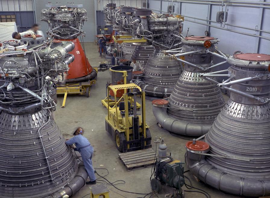
Click image to open its page at the Internet Archive in a new window.
Splitter plates at the turbine exhaust manifold inlet contributed to the uniform distribution of the exhaust gasses. Flow vanes in the exit slots provided uniform static pressure distribution in the nozzle extension. At the time the turbine exhaust manifold was designed, engineers were unable to predict the pressure distribution in the manifold with sufficient accuracy. As the manifold had a fabrication lead time of many months, the turning-vane contour was based on available theory and removable plugs were inserted in the auxiliary turning vanes. Pressure contours could be fine-tuned with various combinations of plugs removed, without the necessity of physically moving the turning vanes.
The following diagram does not seem to reflect the final turbine exhaust manifold configuration, although the turbine exhaust manifold was refined during the F-1 program.

Click image for a 1813x1281 pixel version of this image in a new window.
From page 45 (p. 59 in the PDF) of Liquid Rocket
Engine Nozzles.
Extraction, cleanup, and adaptation by heroicrelics.
Here are a few additional gratuitous diagrams depicting the turbine exhaust manifold, fuel return manifold, and nozzle extension:

Detail of the Thrust Chamber and Nozzle
Extension.
Cleanup and adaptation by heroicrelics.
Click image for a 1897x1157 pixel version of this image in a new window.
Adapted from page 64 (p. 80 in the PDF) of Liquid Rocket Engine
Fluid-Cooled Combustion Chambers.
Extraction, cleanup, and adaptation by heroicrelics.
This photo shows the forward end of the nozzle extension, which incorporates its own attachment flange and flow vanes.

Click image for more information about this picture; opens in a new window.
Picture by heroicrelics.org.
I've marked up a photo of an F-1 engine to assist in the location of various engine features described on this page:
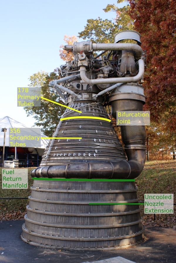
Photo and markup by heroicrelics.org.
And, finally, here's a cut-away diagram of the F-1 rocket engine thrust chamber and nozzle extension:
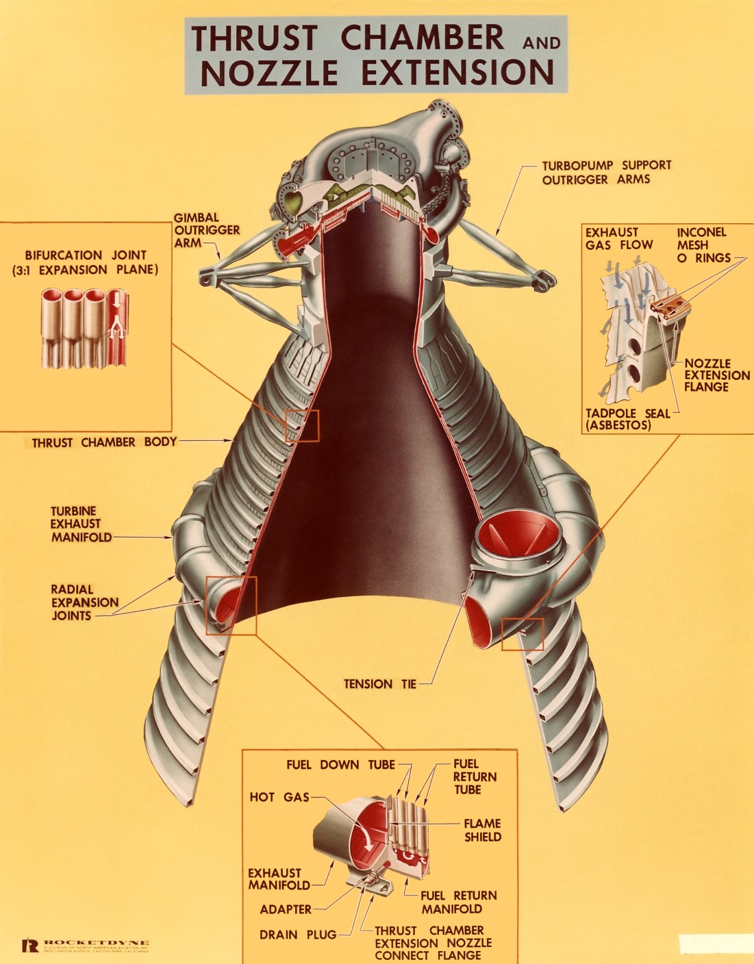
Click image for a 1101x1408 pixel version of this image in a new window.
Photo courtesy Vince
Wheelock.
References
In researching this page, I drew information (including many verbatim text passages) from the following sources:
- Apollo Systems Description, Volume 2 - Saturn Launch Vehicles [direct link to 30M PDF];
- "Design and Development of a 1,500,000-Pound-Thrust Space Booster Engine";
- F-1 Rocket Engine Technical Manual: Engine Data (R-3896-1) [direct link to 19M PDF];
- "Furnace Brazing the F-1 Thrust Chamber for Apollo";
- Liquid Rocket Engine Nozzles (SP-8120);
- Saturn V News Reference.