| Prev |
heroicrelics.org U.S. Space & Rocket Center Site Index RL10 Engine (Old Museum) Gallery |
Next |
dsc18470.jpg
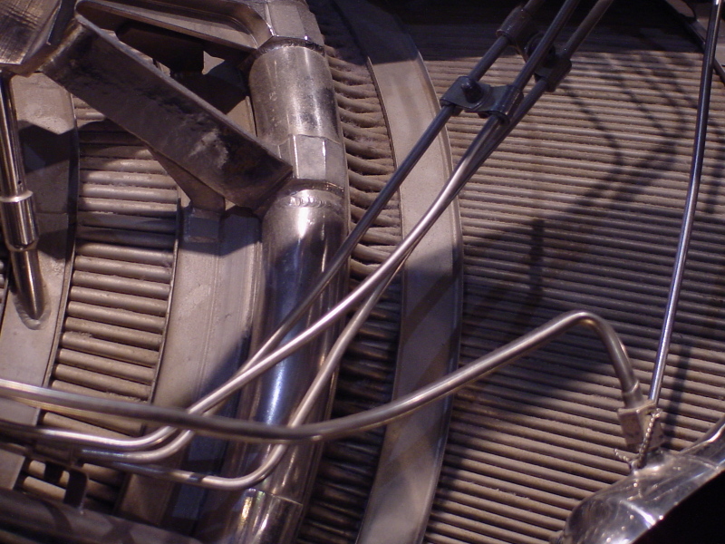
Overall view of the hydrogen inlet manifold.
Liquid hydrogen from the turbopump is routed to this inlet manifold, where it travels down the regenerative cooling tubes to the turnaround manifold at the engine's exit plane and back up to the exit manifold near the forward end of the engine.
The RL10 thrust chamber is constructed of 180 full-length tubes running from the exit manifold to the turnaround manifold, plus an additional 180 tubes running from the inlet manifold to the turnaround manifold. This "pass-and-a-half" construction increases the number of tubes comprising the thrust chamber as the diameter of the nozzle increases, allowing for a high expansion ratio.
| Time picture taken | Sat Jul 15 13:32:29 2006 |
| Location picture taken |
Space Hall "Old" Museum U.S. Space & Rocket Center Huntsville, AL |
| Prev |
heroicrelics.org U.S. Space & Rocket Center Site Index RL10 Engine (Old Museum) Gallery |
Next |