
F-1 Engine Tube Markings
Like most engines of its time, the F-1 engine's thrust chamber is comprised of regenerative cooling tubes. As one might expect from rocket scientists, each of these tubes is numbered for identification purposes; certain tubes on the F-1 are marked in a way so that those of us who are not rocket scientists can identify them as well.
As described in the F-1 Engine Familiarization Training Manual (R-3896-1),
The thrust chamber body is a furnace-brazed, tubular-walled, regeneratively fuel-cooled, bell-shaped chamber. . . . One hundred seventy-eight primary tubes, hydraulically formed from 1-3/32 inch outside diameter Inconel-X tubing, make up the chamber body above the 3:1 expansion ratio plane (approximately 30 inches below the throat centerline plane). Three hundred fifty-six one-inch-outside-diameter secondary tubes of the same material form the chamber from the 3:1 to the 10:1 expansion ratio plane. A raised weld bead with the tube number and a directional flow arrow, identify fuel-up tube No. 1 and fuel-down tubes No. 60 and 120 on the chamber internal faces of the injector end ring and fuel return manifold. External to the chamber the same tubes are similarly identified on reinforcing bands and straps below the thrust chamber throat.
I first became aware of the markings on the F-1 tubes while processing my photos of F-1 engine F-114-2 at Stafford Air & Space:

Click image for more information about this picture; opens in a new window.
Picture by heroicrelics.org.
The markings on the fuel return manifold (i.e., the aft end of the engine proper) are easy enough to spot, but I made this handy reference diagram to help locate the ones near the thrust chamber throat:
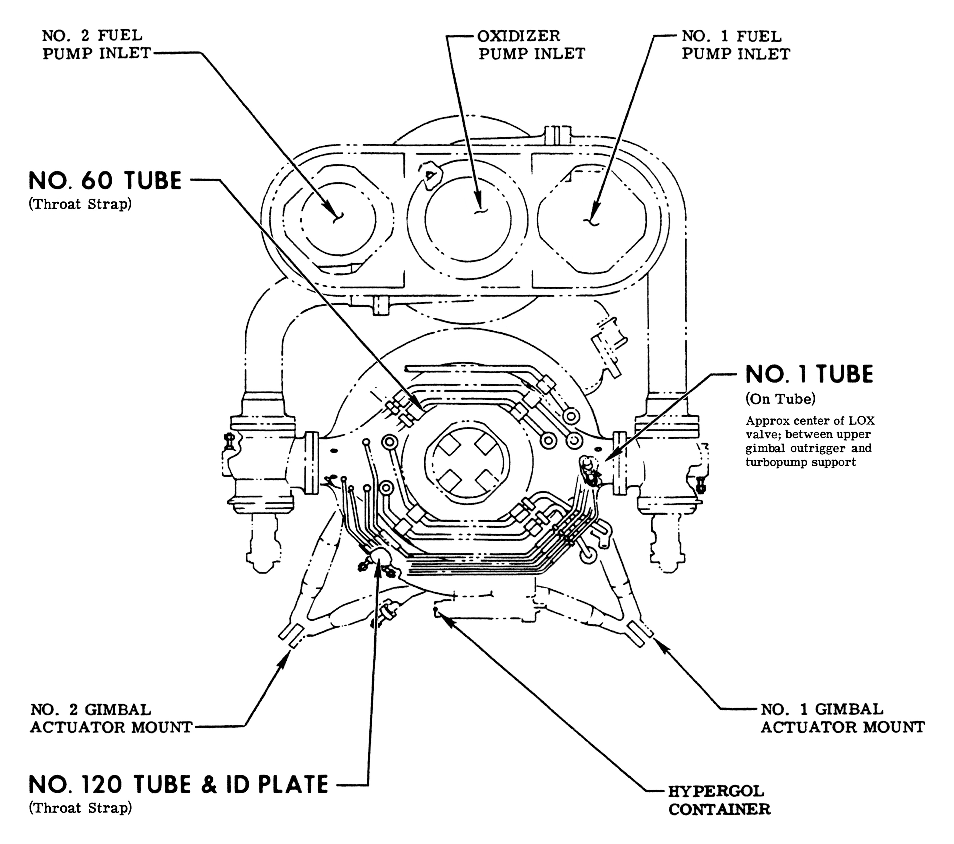
Click image for a 3334x2949 pixel version of this image in a new window.
Adapted from page 2-16 of the F-1 Rocket Engine Data Manual,
located in the archives of the U.S.
Space & Rocket Center. Formerly available from the NASA
Technical Reports Server.
Extraction, restoration, and adaptation by heroicrelics.org.
Although always marked on the Nos. 60 and 120 tubes, the markings themselves seem to vary from one F-1 engine to the next. Here's the No. 60 tube marking from F-1 engine F-6045 at the U.S. Space & Rocket Center:

Click image for more information about this picture; opens in a new window.
Picture by heroicrelics.org.
The tube markings on the injector end ring can be tricky to photograph, as it takes a long lens to be able to capture them. And if the engine's been exposed to the elements for fifty or sixty years, the inevitable corrosion can complicate the matter even more.
Here's a series of photos showing the tube markings on the injector end ring on F-1 engine F-6045 at the U.S. Space & Rocket Center:
The No. 1 tube marking on the injector end ring:

Click image for more information about this picture; opens in a new window.
Picture by heroicrelics.org.
The No. 60 tube marking on the injector end ring:

Click image for more information about this picture; opens in a new window.
Picture by heroicrelics.org.
The No. 120 tube marking on the injector end ring:

Click image for more information about this picture; opens in a new window.
Picture by heroicrelics.org.
Finally, a series of photos showing the tube markings on the throat straps of F-1 engine F-4028 at the U.S. Space & Rocket Center.
The No. 1 tube marking (on the band between the center two straps, partially obscured by a LOX drain line):

Click image for more information about this picture; opens in a new window.
Picture by heroicrelics.org.
The No. 60 tube marking on a throat strap:

Click image for more information about this picture; opens in a new window.
Picture by heroicrelics.org.
The No. 120 tube marking on a throat strap:

Click image for more information about this picture; opens in a new window.
Picture by heroicrelics.org.