| Prev |
heroicrelics.org Stafford Air & Space Museum Site Index F-1 Engine Gallery |
Next |
dsc46666.jpg
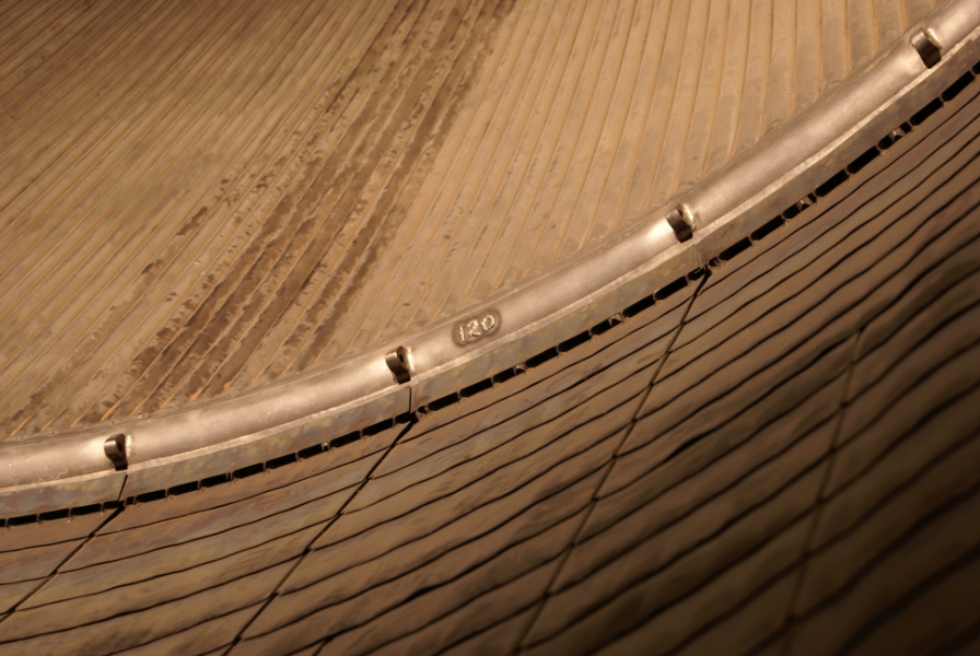
Detail of the inside of the nozzle extension, interface between the engine and the extension, and the fuel return manifold.
Picture 3 of 3.
Note the lugs welded to the inside wall of the fuel return manifold; these were used for attaching a piece of equipment when testing for leaks.
Also note the channels at the forward end of the nozzle extension where the turbine exhaust is vented around the circumference of the extension. The gas generator burns a fuel-rich mixture, resulting in lower combustion temperatures. This relatively cool exhaust flows down the wall of nozzle extension, protecting it from the exhaust gas from the combustion chamber. (According to the F-1 Rocket Engine Technical Manual: Engine Data (R-3896-1), the combustion chamber exhaust is 5,970°F, while the turbine exhaust is a relatively balmy 1,138°F.)
Finally, note the tube 120 raised weld bead in the fuel return manifold.

| Time picture taken | Thu Jul 31 11:31:48 2008 |
| Location picture taken |
Apollo Gallery Stafford Air & Space Museum Weatherford, Oklahoma |
| Prev |
heroicrelics.org Stafford Air & Space Museum Site Index F-1 Engine Gallery |
Next |