| Prev |
heroicrelics.org Marshall Space Flight Center Site Index F-1 Nozzle Extension F-6045 Gallery |
Next |
dsca7168.jpg
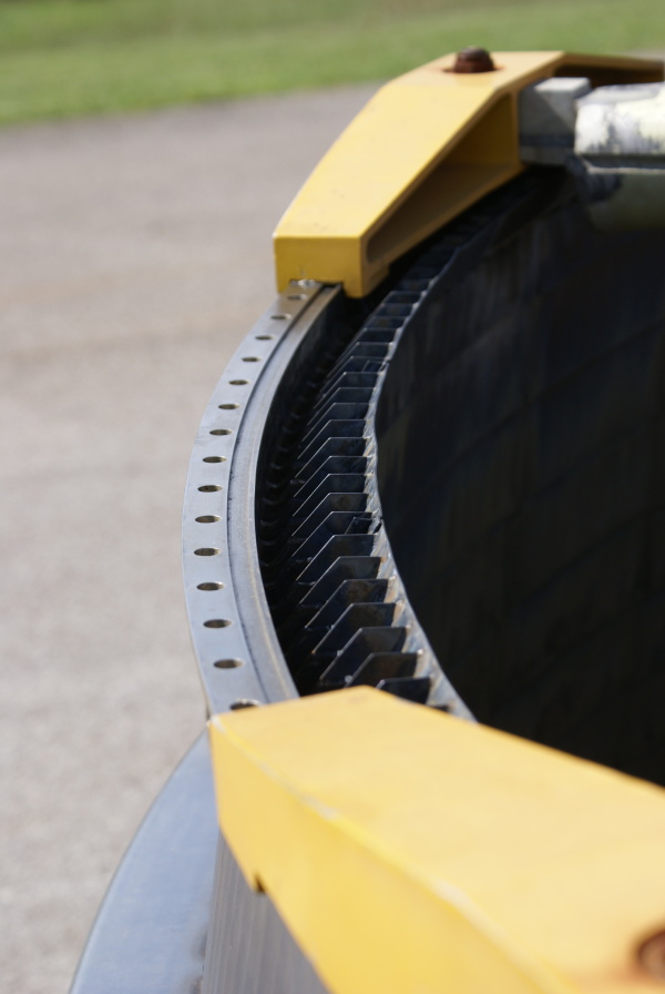
Views of the top of the nozzle extension.
Picture 1 of 5.
The holes in the flange around the outside are for the bolts which would attach the nozzle extension to the thrust chamber, just aft of the turbine exhaust manifold; there are 240 such bolts.
The inner ring with the flow vanes helps direct some of the turbine exhaust gases between the two walls of the nozzle extension and while also allowing some of the gases to flow directly across the surface of the nozzle extension wall, providing film cooling to protect the nozzle extension from the heat of the main combustion gases. The inner ring abuts the fuel return manifold on the thrust chamber's exit plane.

| Time picture taken | Tue Sep 16 10:32:28 2014 |
| Location picture taken |
Building 4205 Marshall Space Flight Center Huntsville, AL |
| Prev |
heroicrelics.org Marshall Space Flight Center Site Index F-1 Nozzle Extension F-6045 Gallery |
Next |