
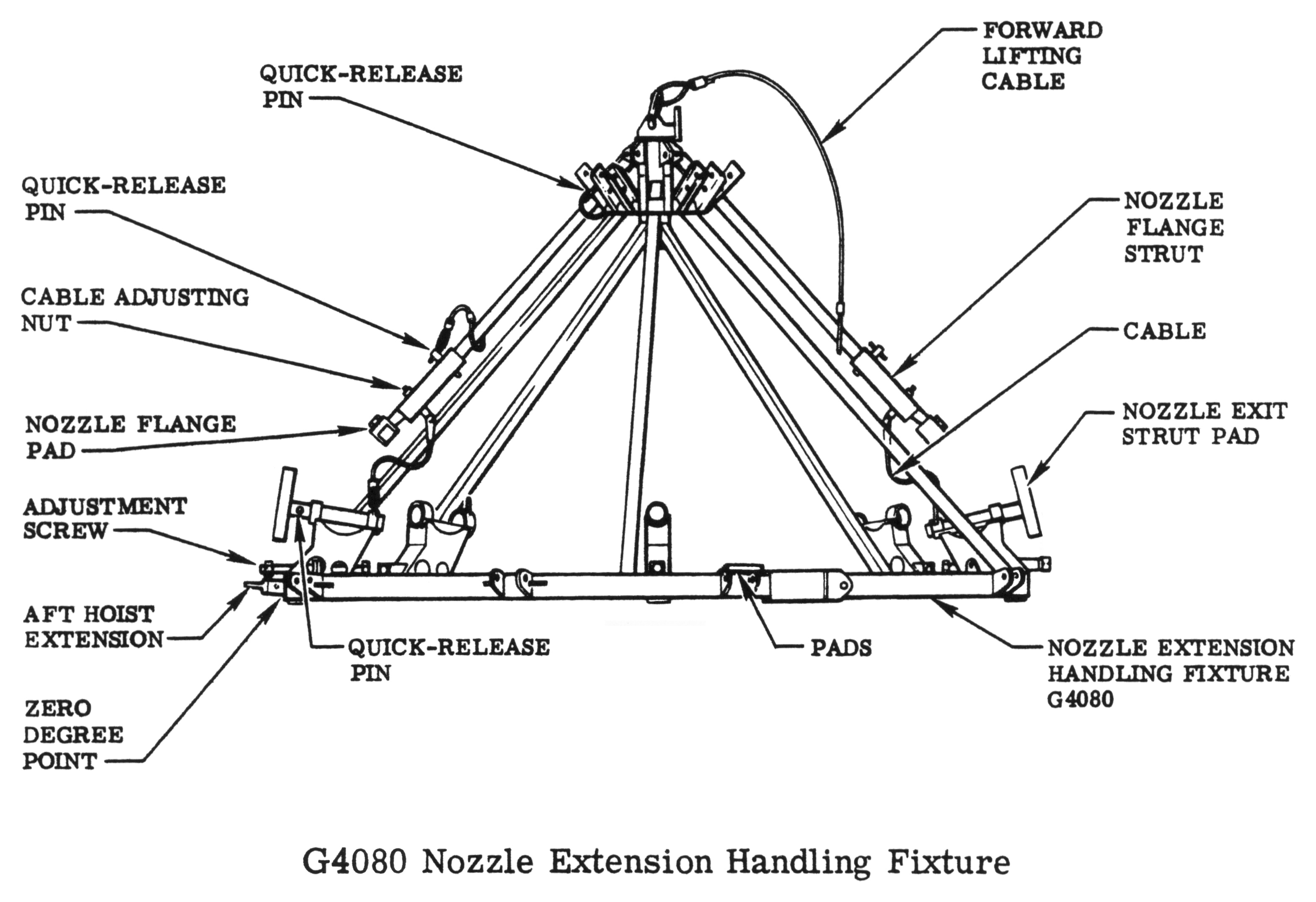
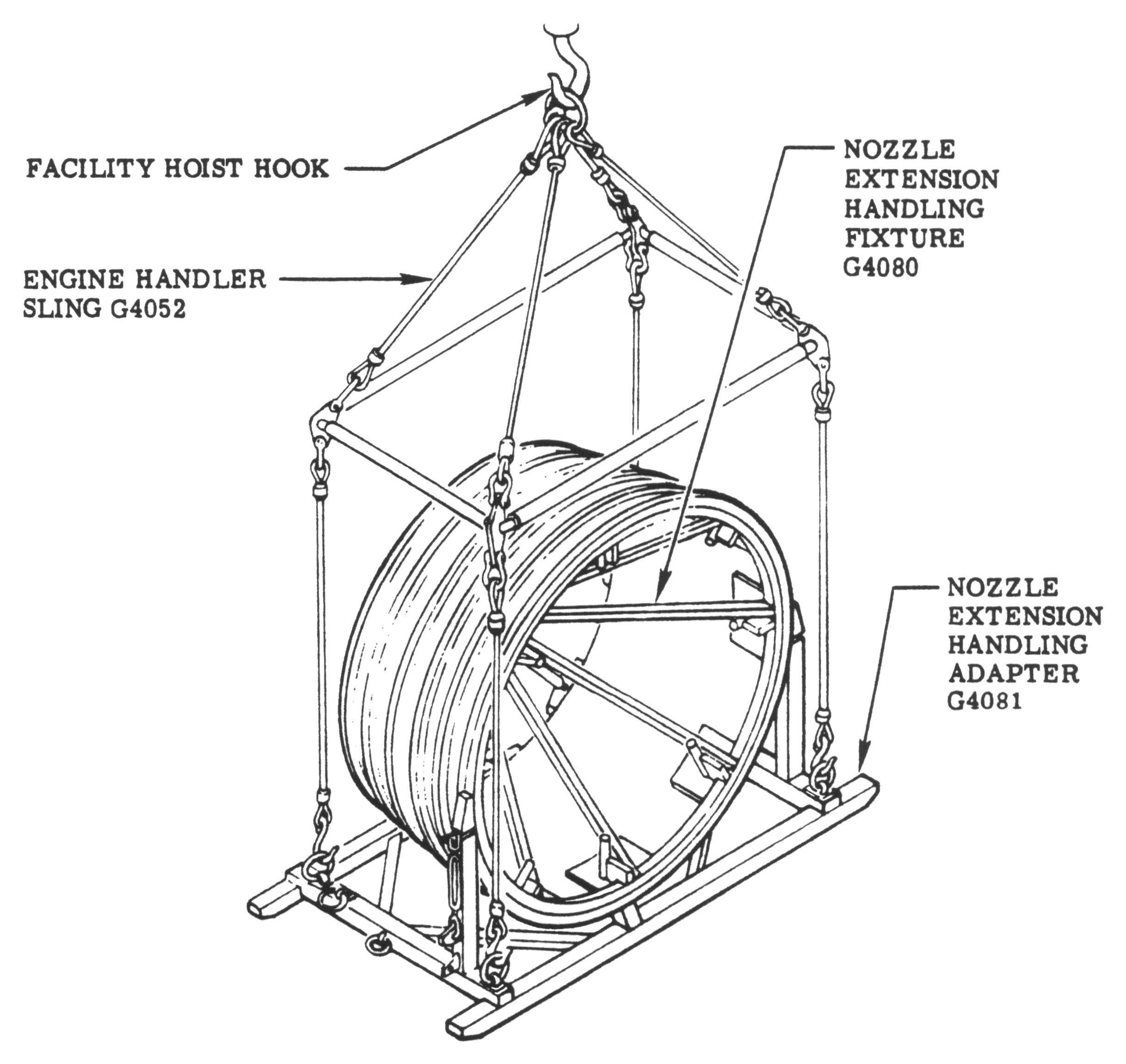
F-1 Engine G4080 Nozzle Extension Handling Fixture
F-1 rocket engine nozzle extensions were mounted onto G4080 Nozzle Extension Handling Fixtures for long-term horizontal storage or for transportation.
The G4080 provided a roughly circular support for the nozzle extension's exit plane; nozzle exit strut pads, rubber-coated pads against which the inner wall of the nozzle extension rested; and flange struts which attached to the forward end of the nozzle extension. The nozzle extension handling fixture also provided attach points to facilitate lifting and handling the nozzle extension.
Click image for a 3141x2153 pixel version of this image in a new window.
Adapted from page 1-18a of the F-1 Rocket Engine Technical Manual:
Transportation R-3896-9, excerpts of which are located in the Young
collection of the Dept. of
Archives/Special Collections, M. Louis Salmon Library, University of
Alabama in Huntsville.
Scan, cleanup, and adaptation by heroicrelics.
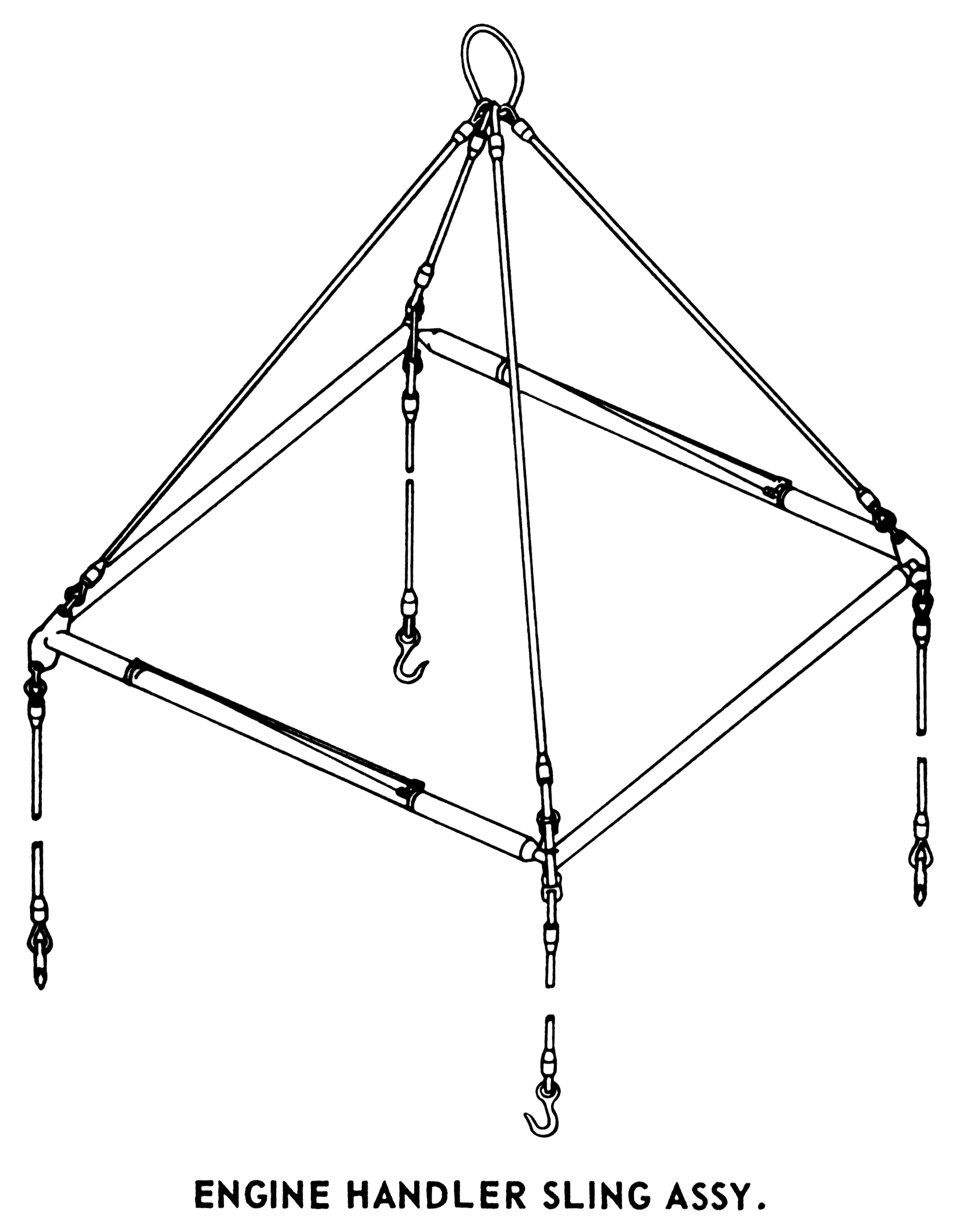
A G4052 Engine Handler Sling Assembly, attached to a nozzle extension's four lifting lugs (located on the forward-most hatband), was used to position a nozzle extension onto the G4080. The Saturn V Launch Vehicle Ground Support Equipment Fact Booklet (MSFC-MAN-100) describes the G4052 as
consist[ing] of four separator bars, eight cables, and a sling. The separator bars have a self-aligning, spherical ball bearing on one end and a flange plate on the other end. The bars are connected together, forming a square, with lockpins. The cables have an eye on one end and a hook on the other. The sling has four cables fastened to a single lift ring. The cables and sling are connected to the separator bars by shackle and lockpins. The sling weighs approximately 600 pounds.
Click image for a 2065x2660 pixel version of this image in a new window.
Adapted from page 5-12 of the Saturn
V Launch Vehicle Ground Support Equipment Fact Booklet
(MSFC-MAN-100). Located in the Saturn V Collection, Dept. of Archives/Special
Collections, M. Louis Salmon Library, University of Alabama in
Huntsville.
Scan, restoration, and adaptation by heroicrelics.
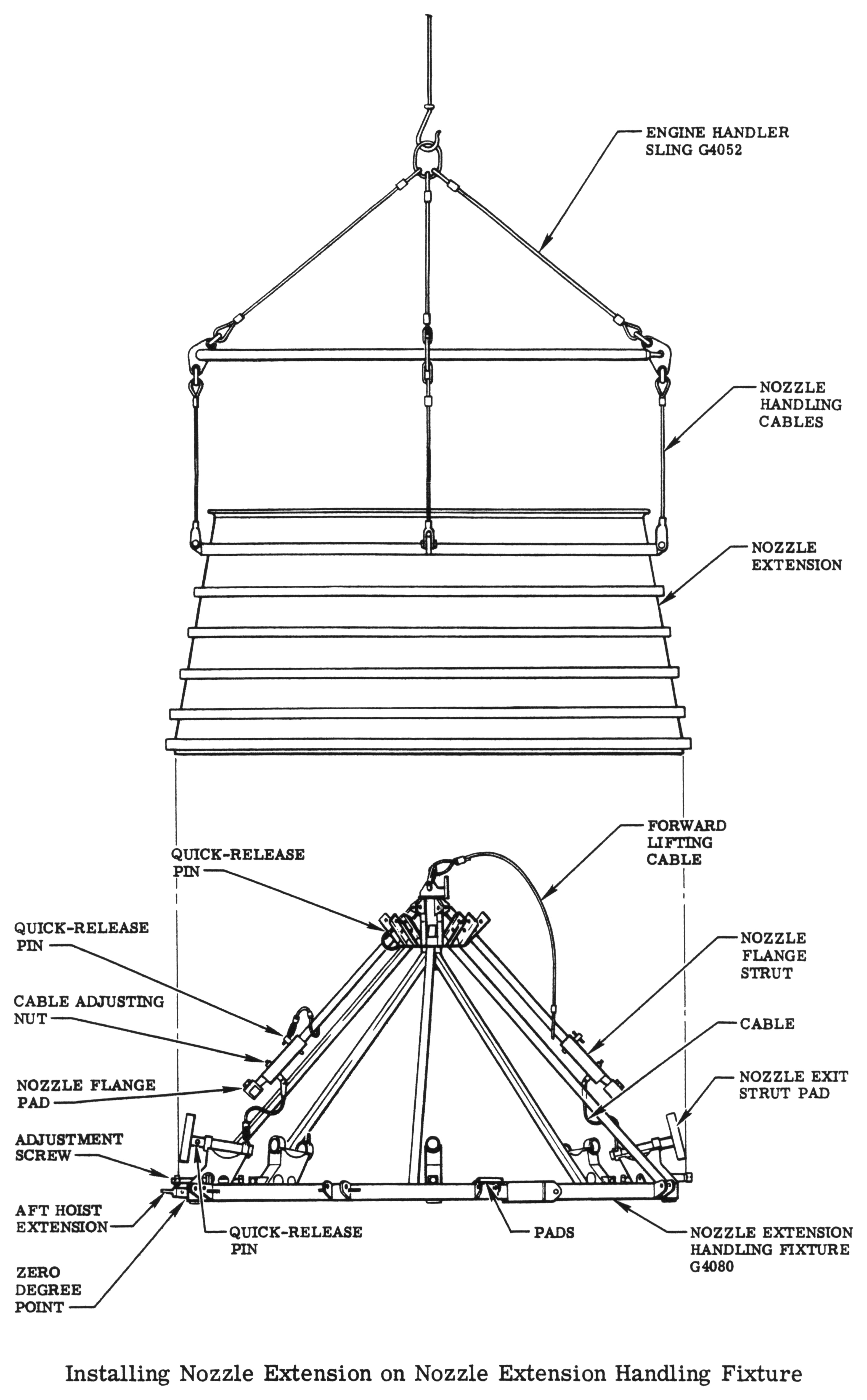
Lifted by the G4052, a nozzle extension would be lowered onto the G4080 until it rested on the nozzle exit strut pads. The nozzle flange struts would be raised, their quick-release pins removed, and the struts extended to attach to the nozzle extension's forward flange.
Click image for a 3141x5073 pixel version of this image in a new window.
From page 1-18a of the F-1 Rocket Engine Technical Manual:
Transportation R-3896-9, excerpts of which are located in the Young
collection of the Dept. of
Archives/Special Collections, M. Louis Salmon Library, University of
Alabama in Huntsville.
Scan and cleanup by heroicrelics.
The rubber-like strut pads leave darker rectangular areas in the nozzle extension (e.g., in three of the walk-around photos of F-114-2 at Stafford Air & Space or three of the walk-around photos of F-6049 at the Udvar-Hazy Center. I am not certain whether these darker rectangles are themselves discolored areas, or whether the strut pads simply preserved the original color and the rest of the interior faded during years of storage.
Page 1-73, Storage Preparation for Thrust Chamber Nozzle Extension, of the F-1 Rocket Engine Operating Instructions notes that earlier models of the nozzle extension (209210, 209210-11, and 209210-21) may be stacked three high on pallets with support provided between pallets, but a later model (209210-31) must be stored singly or as the top unit on a stack. The procedure is not entirely clear, but it appears to be describing loose nozzle extensions, prior to mounting on a G4080.
The G4080 could optionally be mounted be mounted to a G4081 Nozzle Extension Handling Adapter, which allowed for vertical storage or transportation. There were two wedge-shaped fittings on the G4080's bottom circular platform with sockets (at the 7:00 position in dsc67068.jpg), providing attach points for the G4081.

Click image for a 3256x5321 pixel version of this image in a new window.
From page 1-20 of the F-1 Rocket Engine Technical Manual:
Transportation R-3896-9, excerpts of which are located in the Young
collection of the Dept. of
Archives/Special Collections, M. Louis Salmon Library, University of
Alabama in Huntsville.
Scan and cleanup by heroicrelics.
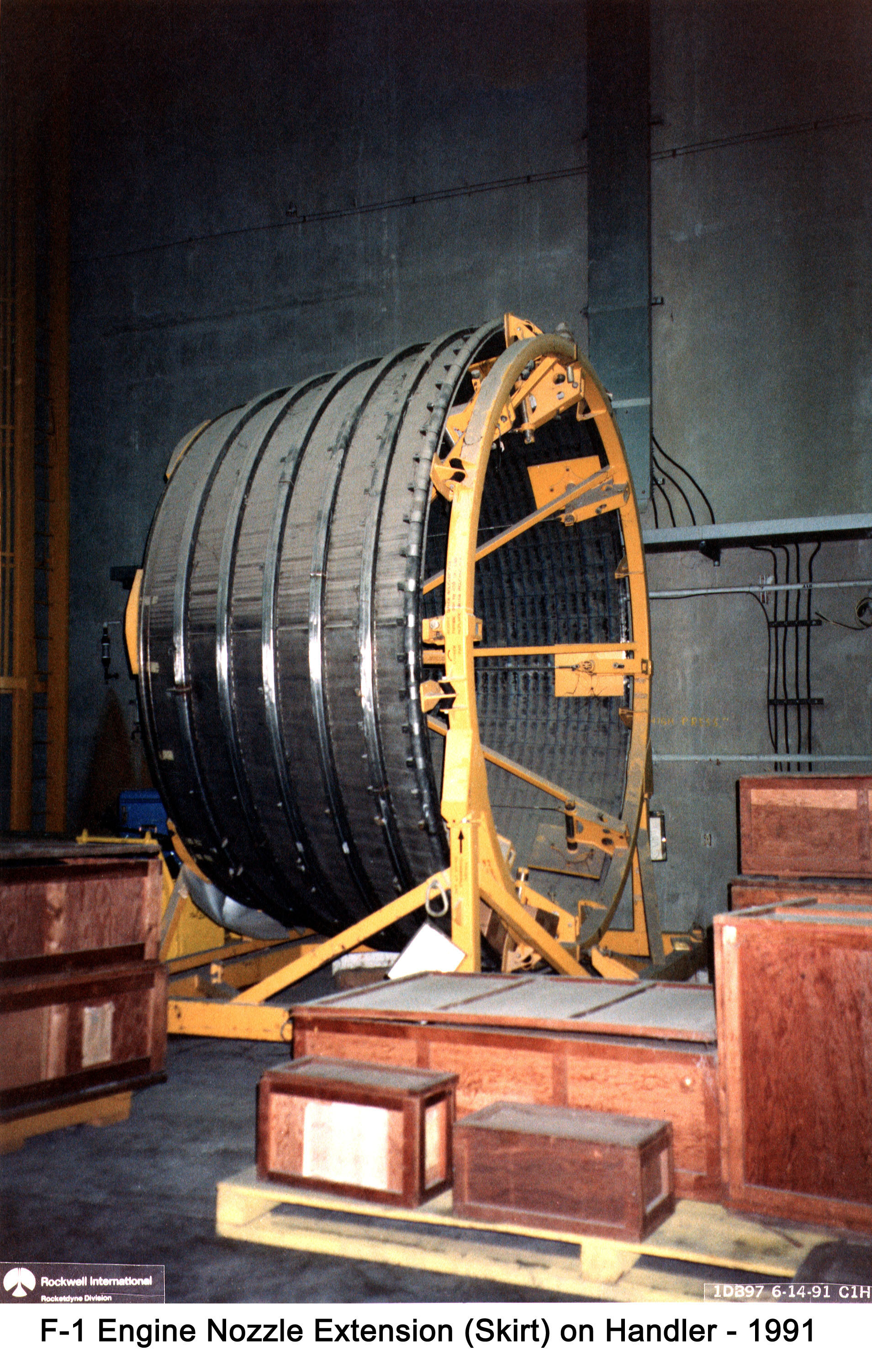
Here is a photo of an F-1 rocket engine nozzle extension with its G4080 Nozzle Extension Handling Fixture and G4081 Nozzle Extension Handling Adapter. One of the wedge-shaped fittings on the G4080's circular platform can be seen where the G4081 attaches (just forward of the black "up arrow").
The caption dates this photo as having been taken in 1991. Alan Lawrie tells me that a number of F-1 engines were audited in 1990 while in environmental storage at the Michoud Assembly Facility, so I assume that this is where this photo was taken.
Click image for a 1909x3003 pixel version of this image in a new window.
Photo courtesy Vince
Wheelock.
Once mounted on a G4081, we see that the G4052 Engine Handler Sling could be reconfigured to move the nozzle extension in this configuration as well.
Click image for a 2435x2300 pixel version of this image in a new window.
Adapted from page 2-2 of the F-1 Rocket Engine Technical Manual:
Transportation R-3896-9, excerpts of which are located in the Young
collection of the Dept. of
Archives/Special Collections, M. Louis Salmon Library, University of
Alabama in Huntsville.
Scan, cleanup, and adaptation by heroicrelics.
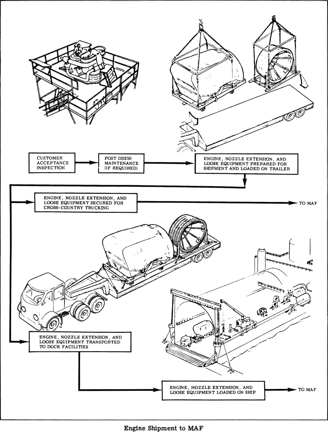
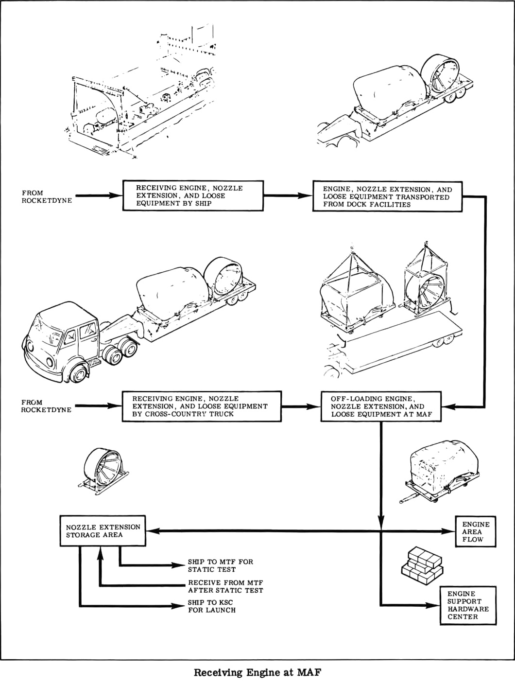
Here are two diagrams depicting the shipment of an engine, along with its nozzle extension in the handling fixture, to the Michoud Assembly Facility (MAF). Note (in the second diagram) that Michoud has a dedicated nozzle extension storage area!
Click image for a 1060x1411 pixel version of this image in a new window.
From page 1-65 of the F-1
Rocket Engine Technical Manual: Engine Data (R-3896-1).
Extraction, clean-up, and adaptation by heroicrelics.
Click image for a 1060x1411 pixel version of this image in a new window.
From page 1-67 of the F-1
Rocket Engine Technical Manual: Engine Data (R-3896-1).
Extraction, clean-up, and adaptation by heroicrelics.
I've only seen two separate nozzle extensions, both at Marshall Space Flight Center; one was being stored temporarily, prior to mating with F-1 engine F-4023 and installation in front of Building 4205. The other was nozzle extension F-6045, formerly mated to F-6049 at the Udvar-Hazy Center. The National Air & Space Museum once had a photo of nozzle extension F-6045 mounted on its G4080, rotated vertically and stored on a G4081.
The only separate nozzle extension of which I am aware that is on permanent public display is at the New Mexico Museum of Space History, which I have not yet visited.