
F-1 Major Configuration Change Points
During one of my visits to the archives of the University of Alabama at Huntsville, I found a memo entitled "F-1 Major Configuration Change Points." As indicated by its title, this memo describes changes made to the F-1 rocket engine:
Internal LetterNorth American RockwellDate:9 March 1971No.:71-12FTo:L.R. DietrichFrom:E. StagersAddress:D/596-152 AB31Address:D/596-152 AB31Phone:3232Subject:F-1 Major Configuration Change PointsThere have been six F-1 major configurations starting with the pre-production R&D engines. The following gives the major features for each configuration, the changes, and the reason for such changes:
- Pre-production R&D engine configuration features which were changed on subsequent production engines:
- Externally tied flexible high pressure ducts
This configuration of high pressure duct utilized flexible metal bellows to provide for relative movement between the turbopump and the main propellant valves. The flexible metal bellows separation loads where restrained by four tie rods with spherical bearings at their ends and attached to a pivot arm which was in turn attached to the rigid section of the duct.
- Soft electrical harness
The electrical harness, made up and routed during engine assembly, consisted of separate wires for each circuit routed in a bundle, spot tied and clamped to the engine at regular intervals to provide support. The only protection from damage of this type of wiring is the individual wire insulation cover.
- Hydraulic control system plumbed with flared tubing, "B" nuts and standard AN fittings
This method of plumbing hydraulic and pneumatic systems was common practice for aircraft and rocket engines at the start of the F-1 engine development program. It provides a convenient method of routing at assembly of tubes required to interconnect the various valves and other components.
- Constant area turbine exhaust manifold
This manifold is attached to the aft end of the thrust chamber and is used to collect the turbine exhaust gas and distribute the gases circumferentially around the inlet to the gas cooled thrust chamber nozzle extension.
- First production configuration engine (F-1001-F-1003)
This configuration block consisted of only three engines which were built and delivered for ground test by the customer. [heroicrelics: This is likely an error; there is evidence that there never was an F-1003.]
- No thermal insulation was provided
Protective thermal insulation was not required for these engines as they were to be tested as single engine and, therefore, would see no heat from adjacent engines as would be encountered in the vehicle application.
- No interface panel was provided
The interface panel was not required for these engines as they were to be tested in a static test stand. The interface panel function is two-fold – first, to provide heat shield closeout with vehicle and second, to establish a uniform connection point for electrical connections between the engine and vehicle.
- Soft electrical harness was replaced by armored electrical harness
R&D testing showed that the soft harness was subject to mechanical damage and heat damage. As an electrical system failure could produce damaging results to the engine and vehicle, the armored harness was developed to provide a higher degree of reliability of the engine system. The armored harness is routed and fabricated in a tooling fixture much the same as a soft harness is fabricated on an engine, with a protective insulation being placed over the wire bundle and then covered with a wire braid to provide protection from both mechanical and heat damage.
- Externally tied high pressure ducts were replaced with internally tied high pressure ducts
R&D testing had shown that the external tie rods were difficult to retain at their ends while providing adequate angulation. However, this was not the major reason for replacement. The prime reason for replacement was to simplify the fabrication and reduce the number of parts required. The internally tied high pressure ducts contained only three parts at each bellows as compared to eight for the externally tied configuration.
- Constant area turbine exhaust manifold was replaced with constant pressure turbine exhaust manifold
The turbine exhaust manifold was redesigned to provide better distribution of the gases to the thrust chamber nozzle extension resulting in elimination of hot spots on the nozzle inner wall and local distortion of the nozzle.
- Replaced hydraulic control flared tube, "B" nuts and AN fitting plumbing with welded, manifolded tubing with bolted flange joints and seal plates
R&D engine testing showed flared tube and "B" nut type joints to be a problem area due to vibration and pressure levels encountered on the F-1 engine.
- Second production configuration engines (F-2003-F-2016)
This configuration block consisted of 14 engines; the first eight were used for ground test by the customer and the remaining six were allocated to the first flight vehicle [heroicrelics: SA-501, which launched Apollo 4].
- G.G. spark ignition system was replaced by pyrotechnic igniters
R&D engine testing showed problems with the spark igniter electrical system components due to the high level of vibration of the F-1 engine.
- Twin elbow LOX dome inlet replaced with single "fish mouth" LOX dome inlet
The inlet was redesigned to improve flow characteristics and reduce the turbopump speed requirements which in turn improves the reliability of the engine.
- Added primary and auxiliary flight instrumentation
The flight instrumentation system consisted of a primary and auxiliary system. The purpose of this being to provide engine data during flight conditions. The auxiliary system was basically redundant or parallel to the primary system. This redundancy was to insure that the data desired would be obtained on the early flights due to the cost of each flight and the inability to re-fly a flight if the data was not obtained.
- Added thermal insulation
The thermal insulation was added as both cluster ground tests and vehicle flights would be performed with these engines.
- Added wrap-around lines across the gimbal plane
The wrap-around lines were added to provide the necessary hydraulic and gas supply and returns between the vehicle and engine.
- Added cast interface panel
The interface panel was added to provide a heat shield closeout between the engine and vehicle. Also to provide a coordinated electrical attach and support between the engine and vehicle.
- Third Production configuration engines (F-2017-F-2028)
This configuration block of engines was allocated in total to flight vehicles and represents the last major configuration block change point.
- Replaced internally tied high pressure ducts with rigid high pressure ducts
The internally tied high pressure ducts proved difficult to fabricate due to electron beam welding problems. This problem was encountered when the internal crosses were "EB" welded to the tube wall on either side of the bellows.
- Replaced cast interface panel with fabricated panel
The cast interface panel proved too difficult to fabricate. The problem was due to the castings being of a large size and of high temperature high strength materials. These castings were further complicated due to large, thin web sections.
- Added stage static firing instrumentation
This system was added to provide stage static test data to insure engine vehicle reliability.
- Fourth production configuration engines (F-2029-F-2042)
This configuration block of engines does not represent a major design change point in terms of major component hardware redesign. The changes made at this block are mostly minor component hardware changes resulting from engine and component PFRT and FRT [heroicrelics: preliminary flight rating test and flight readiness test] testing.
- Added thrust "OK" pressure switch
These switches (3) were added to provide flight onboard engine monitoring capability.
- Incorporated a number of detail component design improvements
These design changes were minor and the results of engine and component PFRT and FRT testing. These changes were made to improve the reliability confidence of the engine.
- Fifth production configuration engine (F-2043 and subs)
This configuration block change was made to delete the hardware no longer required for flight vehicles.
- Deleted auxiliary flight instrumentation
The redundancy of this system was no longer required as ample data had been or would be acquired from earlier flight engines. Also the deletion of this system resulted in less instrumentation openings required and therefore improved reliability by reducing the number of openings having seals as a potential leak.
E. Stagers
Large Engine Systems DesignES:mb
cc: P. Coffman (3)

The memo also included a chart, entitled "F-1 Program Milestones", listing such events as the awarding of the NASw 16 and 18734A contracts; first engine mainstage test; delivery of the first F-1 engine, F-1001; completion of the qual and qual II reliability demonstrations; and the flights of AS-501 and AS-502:
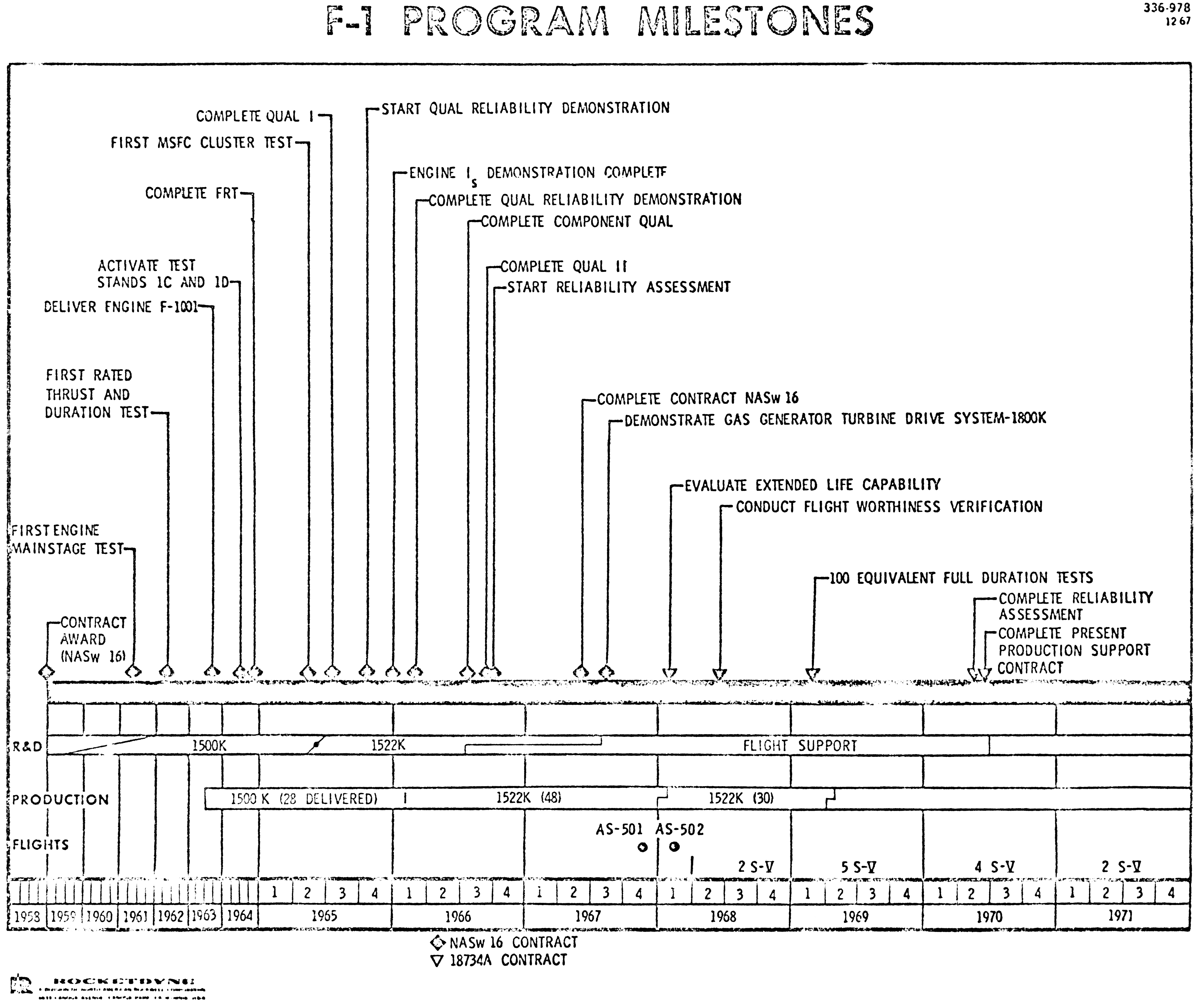
Click image for a 5645x4750 pixel version of this image in a new window.
Scan and clean-up by heroicrelics.org.
F-1 Engine Serial Numbers
Note that the serial numbers in this memo refer to Rocketdyne's internal serial numbers. Their serial numbers followed a more-or-less normal progression sequence (the only break being between the F-1xxx series and the F-2xxx series).
As detailed in Alan Lawrie's Saturn, NASA used a different numbering scheme. While the final three digits of the engines stayed the same, the first digit differed for the later serial numbers. For the most part, it seems that NASA incremented the first digit to correspond to configuration changes described above, although NASA further divided the F-2003-F-2016 range into two ranges:
| Rocketdyne Serial No. | NASA Serial No. |
|---|---|
| F-1001 to F-1002 | F-1001 to F-1002 |
| F-2003 to F-2010 | F-2003 to F-2010 |
| F-2011 to F-2016 | F-3011 to F-3016 |
| F-2017 to F-2028 | F-4017 to F-4028 |
| F-2029 to F-2042 | F-5029 to F-5042 |
| F-2043 to F-2098 | F-6043 to F-6098 |
In a private email exchange, Lawrie tells me that he has found no Rocketdyne records for engine F-1003; additionally, a retired Rocketdyne engineer told him that F-1003 never existed.
In support of Lawrie's evidence, it certainly makes sense that the engine was never manufactured (perhaps being a typo in this original memo) because the final three digits of the Rocketdyne serial numbers are otherwise unique. It would be odd for there to be both an F-1003 and an F-2003.
Visually-Prominent Configuration Changes
Of the changes described in this memo, several are visually prominent and can be seen on F-1 engines on display in museums across the country:
- Changes to the thermal insulation.
- Changes to the turbine exhaust manifold.
- Addition of an interface panel.
- Changes to the LOX dome inlet.
- Changes to the high pressure ducts
Changes to the Thermal Insulation
The F-1 engine thermal insulation was a set of external coverings used to protect the engine from hot gases. The insulation was installed prior to launch and for certain types of static firings.
Today, all but one of the remaining F-1 engines are displayed without their thermal insulation. One engine, on display at the Powerhouse Museum in Sydney, Australia, is displayed with one (or part of one) if its insulation jackets.
Since the thermal insulation was removable, I'm not classifying it as a "visually-apparent" change, per se. However, the thrust chamber and the nozzle extension were both fitted with tabs and studs used to mount the insulation:

Click image for more information about this picture; opens in a new window.
Photo by heroicrelics.org.
When looking at earlier engines, the sides of the thrust chamber seem strangely smooth, because no such tabs were present:

Click image for more information about this picture; opens in a new window.
Photo by heroicrelics.org.
Changes to the Turbine Exhaust Manifold
The turbine exhaust manifold wrapped around the aft end of the F-1 engine proper, channelling the relatively cool turbine exhaust gases to the nozzle extension, where it was used to provide film cooling to the walls of the extension.
I was rather excited when I read this change to the turbine exhaust manifold: Constant area turbine exhaust manifold was replaced with constant pressure turbine exhaust manifold. Long ago, I'd noticed a difference in the turbine exhaust manifold and wondered about it. When I first read this memo, I thought I'd found my answer.
On earlier engines, the heat exchanger and turbine exhaust manifold formed an inverted "T" shape:

Click image for more information about this picture; opens in a new window.
Photo by heroicrelics.org.
On later engines, this formed an inverted "Y":

Click image for more information about this picture; opens in a new window.
Photo by heroicrelics.org.
When I first read this memo, I assumed that the "T"-shaped exhaust manifold was the older, constant-area manifold and the "Y"-shaped exhaust manifold was the newer, constant-pressure manifold. Alas, I read the memo too quickly: The change was made effective F-1001, but F-1001 still has the "T"-shaped manifold:

Click image for more information about this picture; opens in a new window.
Photo by heroicrelics.org.
Alan Lawrie tells me that the "Y"-shaped turbine exhaust manifold was implemented starting with F-3011, which was part of the second block of production engines. Unlike any of the other blocks of engines, NASA assigned two serial number ranges to this block (F-2003 through F-2016) of engines, and the second range of NASA serial numbers starts with F-3011. Presumably, NASA considered the change to the turbine exhaust manifold sufficiently significant to increment the first digit of the serial number.
F-2009, below, is part of the first portion of the second block of production engines, and still has the "T"-shaped turbine exhaust manifold:

Click image for more information about this picture; opens in a new window.
Photo by heroicrelics.org.
So, while this is a visually-prominent change, at the current time I am unable to explain this change in the turbine exhaust manifold shape.
Addition of an Interface Panel
No interface panel was initially provided, later adding a cast interface panel, and finally the cast interface panel being replaced with a fabricated interface panel.
The cast interface panel was only included with 14 engines (Rocketdyne F-2003 through F-2016), of which five survive today. Two of these are mounted on KSC's Saturn V, two of these are the USSRC's Saturn V, and one is displayed on an elevated mount at the Kansas Cosmosphere. The manner in which the engines are displayed makes it difficult to get a good look at the interface panel, but the Cosmosphere's engine definitely has a different appearance from the more familiar fabricated interface panel:

Click image for more information about this picture; opens in a new window.
Photo by heroicrelics.org.
The fabricated interface panel is easy enough to identify due to the plethora of rivets and fasteners (also see my F-1 Engine Interface Panel photo set at MSFC's F-1 engine disassembly):

Click image for more information about this picture; opens in a new window.
Photo by heroicrelics.org.
Although the cast interface panel was only supplied with a few early engines, the cast interface panel under the guise of being a "simplified interface panel" was poised to make a comeback in the F-1A rocket engine. The goal of the F-1A was to provide a modest increase in thrust while reducing complexity (and therefore cost). F-107-1, an R&D engine, has the same type of interface panel as was present on Rocketdyne's F-1A engine mockup vehicle interface.

Click image for more information about this picture; opens in a new window.
Photo by heroicrelics.org.
I didn't initially recall seeing any single F-1 engine displays with no interface panel, although a review of my photos shows that F-1001 at the National Air & Space Museum has no interface panel, and it appears that at least one of the engines on S-IC-T at the Kennedy Space Center is mounted without an interface panel.
A clearer case of no interface panel is this crop of my photo of F-1 engine mock-up FM-101:
Click image for a 1739x1331 pixel version of this image in a new window.
Scan and clean-up by heroicrelics.org.
Changes to the LOX Dome Inlet
While I had either noticed the external physical differences described in this memo or been aware of the actual design changes for the other configuration changes in this section, and even though I'd written a page about the F-1 engine LOX dome, I'd never read about the change to the LOX dome inlet or noticed this difference in any of the F-1 engines I'd seen.
Here's a photo of the final configuration of the LOX dome inlet (referred to above as the "fish mouth" inlet):

Click image for more information about this picture; opens in a new window.
Picture by heroicrelics.org.
Since beginning this research project, I've actually seen a number of photos of F-1s with the twin-elbow LOX dome inlet. It's unclear whether the F-1 in this photo is a development engine or an engine mockup. With the twin-elbow LOX dome inlet and lack of interface panel, this is clearly an early configuration.
Click image to open its page at the Internet Archive in a new window.
Another photo of the twin-elbow LOX dome inlet is on this crop of my photo of F-1 engine mock-up FM-101:

Click image for a 1815x1499 pixel version of this image in a new window.
Scan and clean-up by heroicrelics.org.
The twin-elbow LOX dome inlet is also evident in this early F-1 engine system diagram (circa October 1959):
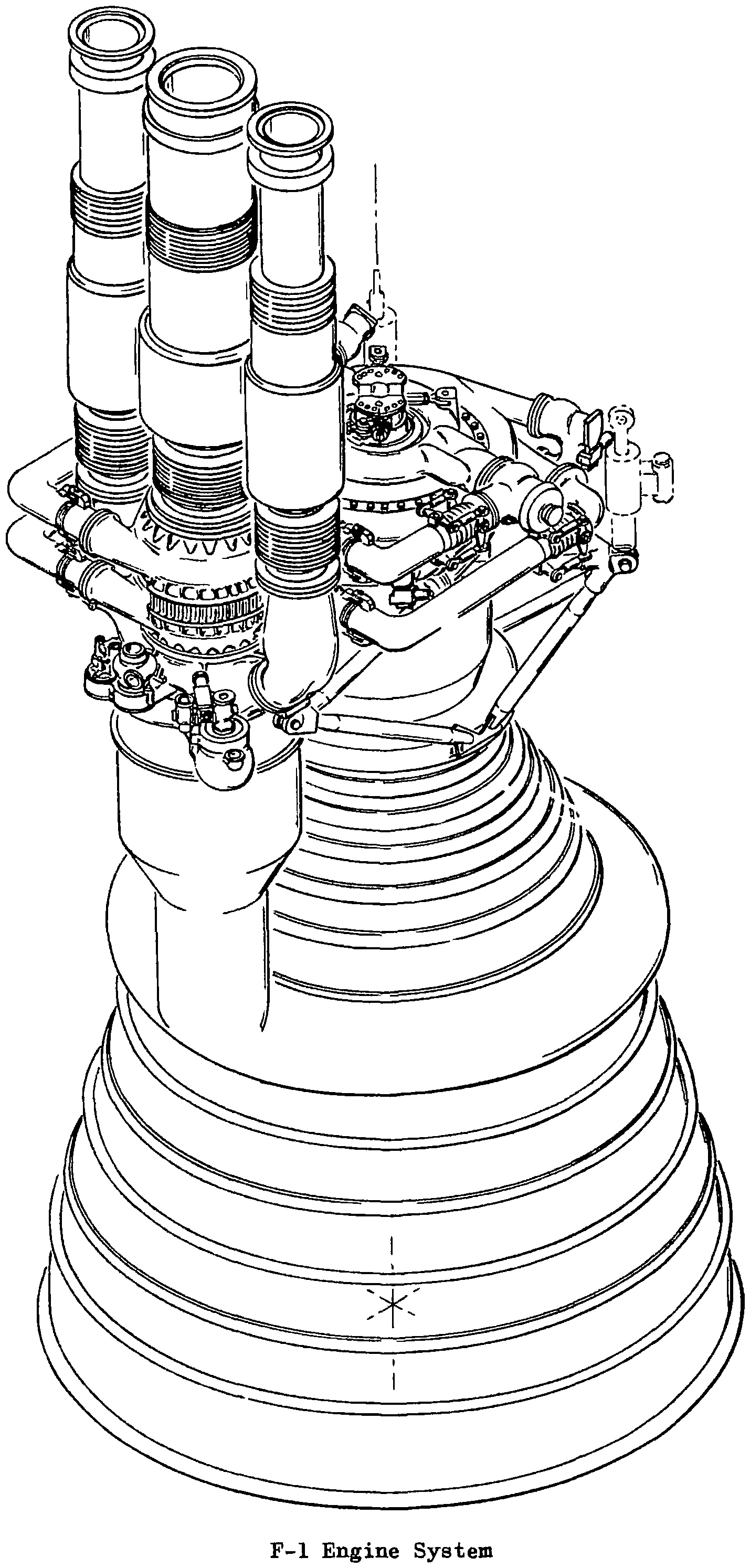
Click image for a 1429x2988 pixel version of this image in a new window.
Taken from page 63 (p. 76 in the PDF) of F-1
Thrust Vector Control Study
Extraction and clean-up by heroicrelics.org.
Now that you know what to look for, the twin-elbow inlet can just barely be discerned in this photo:

Click image for more information about this picture; opens in a new window.
Photo by heroicrelics.org.
The S-IC stage at the U.S. Space & Rocket Center has two engines with twin-elbow LOX inlets.
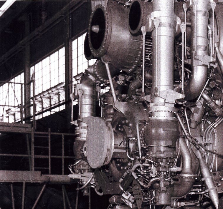
Changes to the High Pressure Ducts
The high-pressure ducts are the large-diameter pipes which carry high-pressure propellants from the turbopumps to the main propellant valves, on their way to LOX dome and the fuel manifold, respectively.
The first two configurations featured flexible high-pressure ducts which employed bellows to absorb vibrations from the turbopump. These ducts were initially externally tied and then internally tied. In the final configuration, the flexible ducts were replaced with rigid ducts.
I'm not a rocket scientist, and I don't have an engineering background, so I initially didn't really know what the term "tied" referred to. Eventually, it occurred to me that my car's front wheels had "tie rods". While I didn't really know what they did, either, a bit of Googling informed me that tie rods are used to resist tension, which is a pulling force (the opposite of compression). So, the tie rods on the ducts prevent the bellows from separating or stretching beyond specifications.
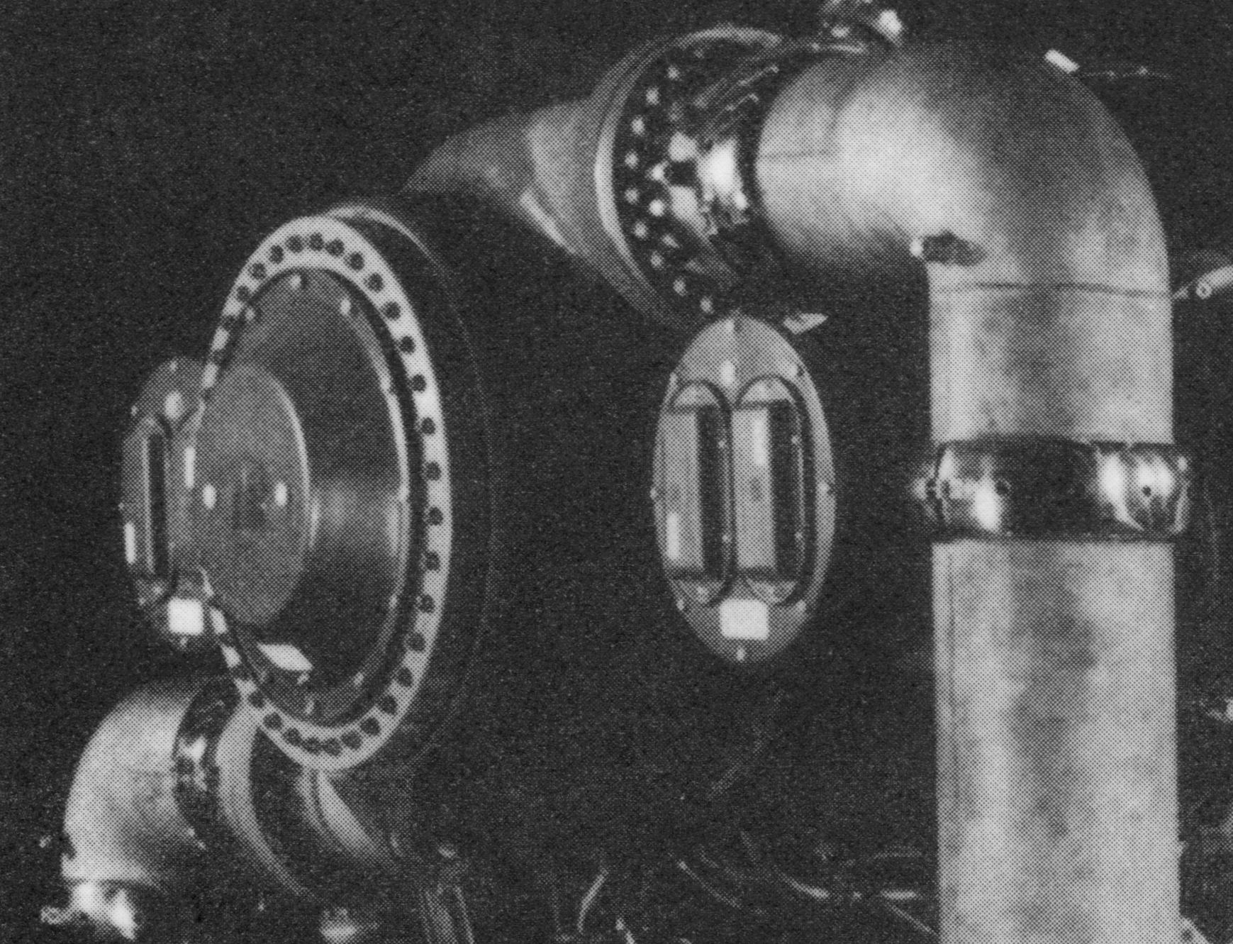
I asked a retired Rocketdyne engineer about this, and he kindly provided a photo of an F-1 engine featuring externally tied high-pressure ducts, which cleared things up for me:
Externally-tied F-1 engine high-pressure ducts
Photo courtesy Vince
Wheelock.
The October 1959 F-1 engine system diagram above shows what appears to be an earlier concept for the externally-tied ducts.
Of course, one can't see the tie rods when they're located internally, but an example of the internally tied ducts is F-1001:

Click image for more information about this picture; opens in a new window.
Photo by heroicrelics.org.
In the photo above, both bellows on the LOX high-pressure duct have covers, but one of the bellows is visible near the bottom of the fuel high-pressure duct. I'd previously noticed the silver caps/bands on the high-pressure ducts on some of these early engines, but had not previously noticed the bellows.
When I later photographed F-2003, I made certain to get photos of the bellows:

Click image for more information about this picture; opens in a new window.
Photo by heroicrelics.org.
Both the externally- and internally-tied fuel high-pressure ducts were straight. When they were replaced with the rigid high-pressure ducts, the fuel ducts became "U"-shaped (while the LOX high-pressure ducts remained straight):

Click image for more information about this picture; opens in a new window.
Photo by heroicrelics.org.
The memo doesn't address why the bellows were no longer needed, or why the fuel high-pressure duct became "U"-shaped. However, I find it interesting that when the fuel line on the J-2 rocket engine augmented spark igniter was redesigned due to the problems experienced on SA-502 (Apollo 6), a straight, flexible bellows was replaced by a rigid line employing several bends, just as the straight, flexible duct employing a bellows on the fuel high-pressure duct was replaced a with a rigid duct with several bends.