
F-1 Engine Injector Baffles
One of the most prominent features on F-1 rocket engine injector face are the baffles:

Click image for more information about this picture; opens in a new window.
Picture by heroicrelics.org.
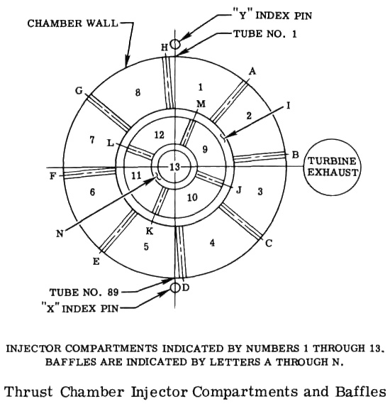
The F-1's injector has two circular (or circumferential) and 12 radial baffles which divide the injector face into 13 compartments. These compartments are identified numerically, 1 through 13, and the baffles are identified alphabetically, A through N. The 12 radial, fuel-cooled, copper baffles are supplied with fuel by the outer circular baffle to which they are brazed. Each baffle is 3 inches tall.
Adapted from page 1-9A of the F-1 Engine Familiarization Training
Manual, located in the archives of the U.S.
Space & Rocket Center. A superset of this document is also available
from archive.org.
Extraction, adaptation, and cleanup by heroicrelics.
Cleanup and adaptation by heroicrelics.
The baffles were added to the injector to combat combustion instability. Since a rocket engine is basically a controlled explosion, it's important to produce combustion which is "dynamically stable"; that is, has predictable combustion which will not create hot spots (and thereby melt the interior of the engine) or burn so rough as to tear the engine apart. The baffles alter the acoustic resonance characteristics of the combustion chamber, dampening tangential and transverse combustion instability shock waves generated during combustion.
The F-1's baffle configuration was determined with great care: A total of 15 different baffle configurations, with the number of compartments ranging from 3 to 81 and the length of the baffles ranging from 3 to 10 inches, were tested; a number of injector configurations with no baffles whatsoever were also tested. The baffle configuration shown above, along with changes to the propellant injection orifices, provided stable combustion and damped out induced instability.
The injector itself consisted of a CRES (corrosion-resistant steel; more commonly known outside the aerospace industry as stainless steel) body with 31 ring grooves, 16 fuel ring grooves alternating with 15 oxidizer ring grooves. Fourteen copper rings containing the fuel orifices and the 2 circular copper baffles were brazed to the fuel ring grooves. Fuel feed passages from the fuel injector manifold supplied fuel to the fuel ring grooves. The outer circular baffle then supplied cooling fuel to the radial baffles.
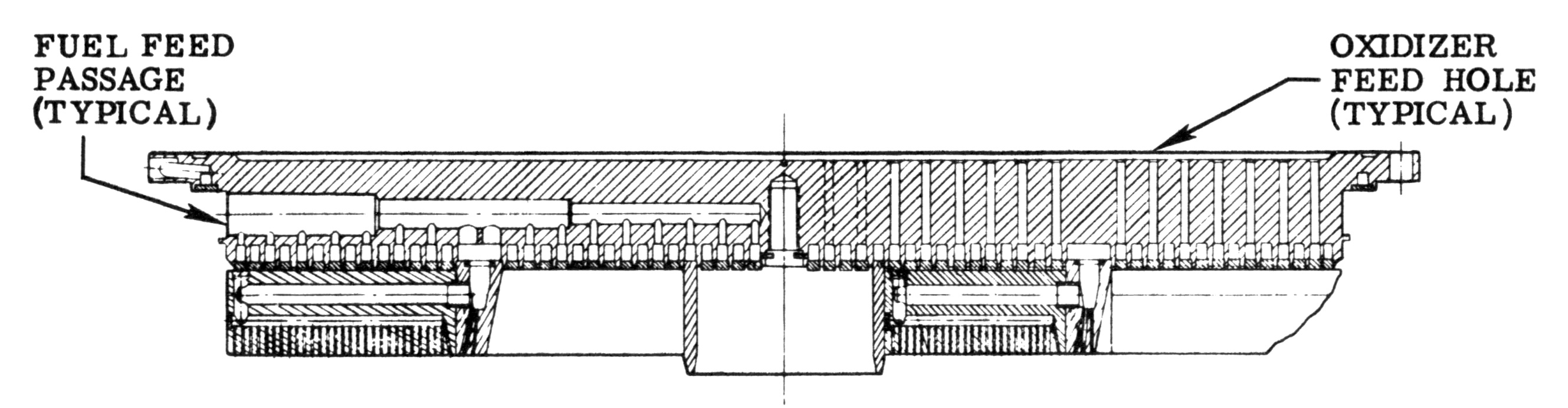
Click image for a 2658x691 pixel version of this image in a new window.
Adapted from p. 1-2 of the F-1 Rocket Engine
Technical Manual Supplement (R-3896-1A)
Adaptation by heroicrelics.
The following diagram also shows how the outer circular baffle feeds both the inner and outer radial baffles:

Detail of the Injector
cut-away.
Cleanup and adaptation by heroicrelics.
In the final configuration, all of the baffles where dump cooled; that is, fuel was circulated through the interior of the baffle, cooling the baffle, and the fuel was then was discharged into the combustion chamber. This is similar to the regenerative cooling scheme used to cool the thrust chamber, but differs in that the regenerative cooling fuel is discharged through the injector and utilized as a propellant.
The dump-cooling orifices can be seen in this photo of a single radial injector baffle:
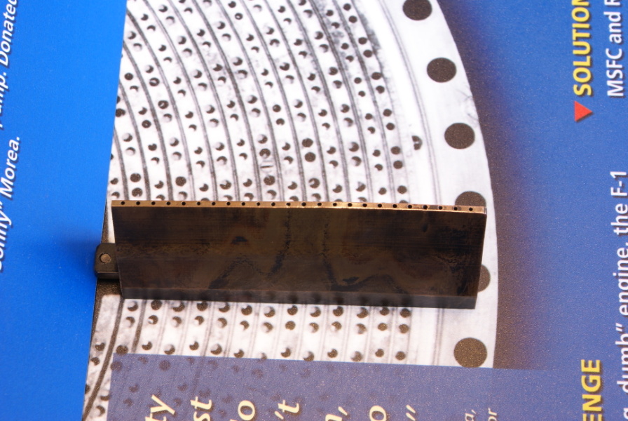
Click image for more information about this picture; opens in a new window.
Picture by heroicrelics.org.
Here's a cut-away diagram of an earlier baffle design, where only the radial baffles were dump cooled; the circular baffles regeneratively cooled. It gives an idea of the fuel flow from the circular baffles and through the inner and outer radial baffles:
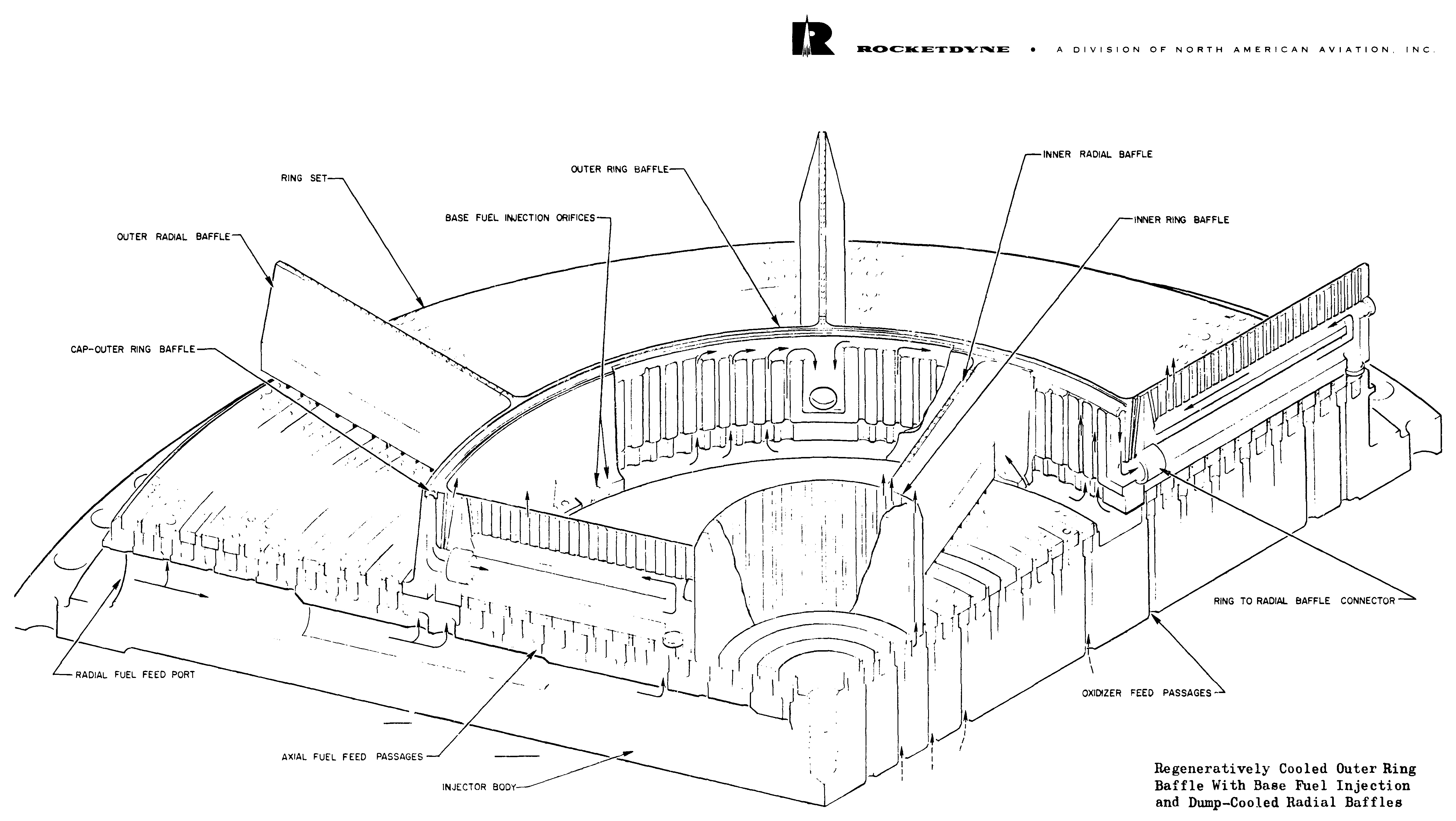
Click image for a 5196x2932 pixel version of this image in a new window.
From p. 112 (p. 126-127 in the PDF) of History:
Project First, F-1 Combustion Stability Program, Volume 3, Book 2
[direct link to 8.8M PDF].
Extraction and cleanup by heroicrelics.org.
And finally, two additional diagrams of the fuel flow through the radial baffles. They largely duplicate information contained in diagrams above, but are gratuitously included on this page (I'm willing to face the criticism that I've included too many F-1 rocket engine diagrams on my site ...)
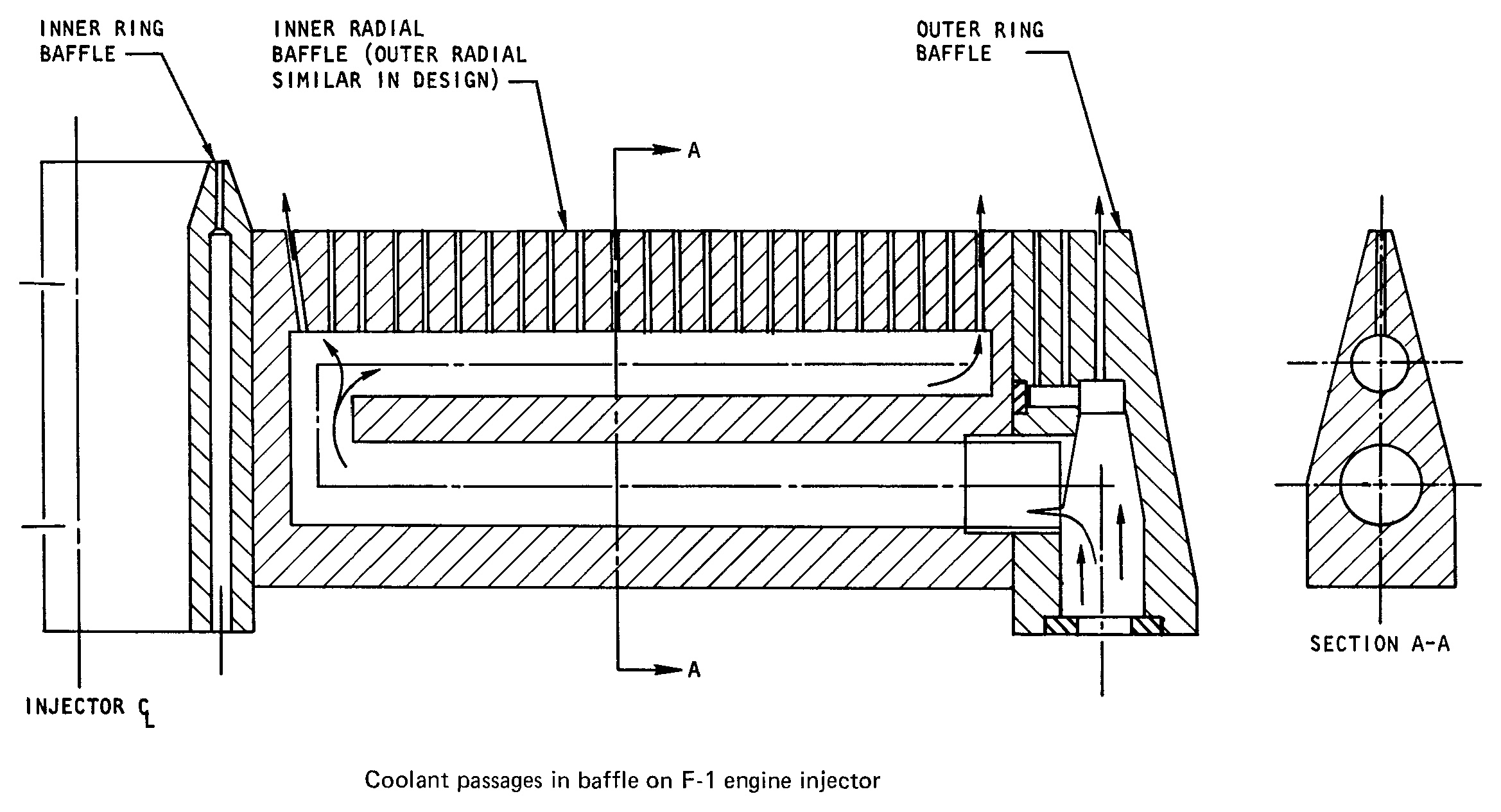
Click image for a 2338x1265 pixel version of this image in a new window.
Adapted from p. 37 (p. 46 in the PDF) of Liquid Rocket Engine
Combustion Stabilization Devices.
Extraction and adaptation by heroicrelics.org.
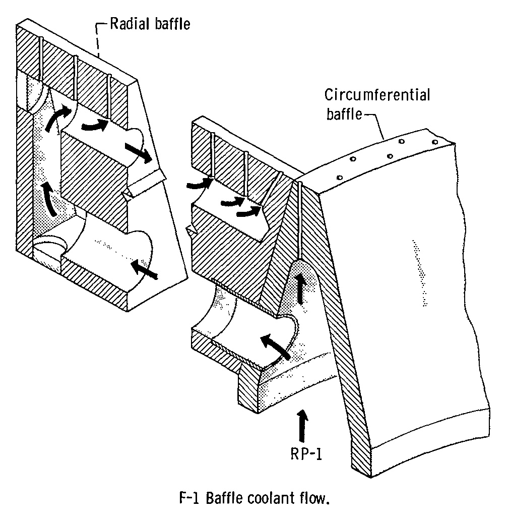
Click image for a 1010x1029 pixel version of this image in a new window.
From p. 30 (p. 33 in the PDF) of M-1 injector
development - Philosophy and implementation.
Extraction and cleanup by heroicrelics.org.