
General Saturn IB Diagrams
I come across many Saturn IB diagrams which, while interesting, are not so interesting that they necessarily merit their own separate page. I have created this page as a repository for such diagrams.
Saturn IB Art
I'll start off with a couple of diagrams which are more artistic than technical.
Here's an early rendering of a Saturn IB on the pad:
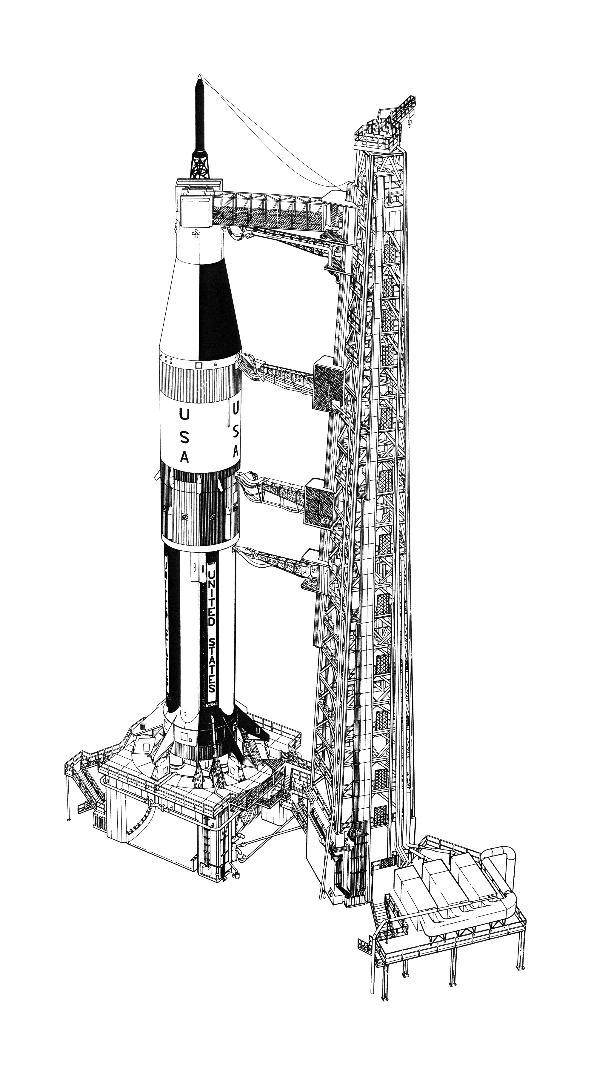
Click image for a 1980x3600 pixel version of this image in a new window or click here for this image as an
11"x20" (6600x12,000), 8.3 megabyte PDF.
From the heroicrelics library.
Scan and cleanup by heroicrelics.
Many of these early Saturn IB drawings depict early Saturn IB concepts, with a checkerboard roll pattern painted on the Spacecraft-Lunar Module Adapter (SLA), turbine exhaust fairings (present only on SA-201 and SA-202, the first two Saturn IBs, whose first stages were actually converted Saturn I first stages), and engine shrouds (present only on SA-201, the first Saturn IB).
If you look closely, you'll see the "SA-201" serial number painted on a fuel container in the diagram above. The diagram shows the engine shrouds, but the turbine exhaust fairings seem to be missing.
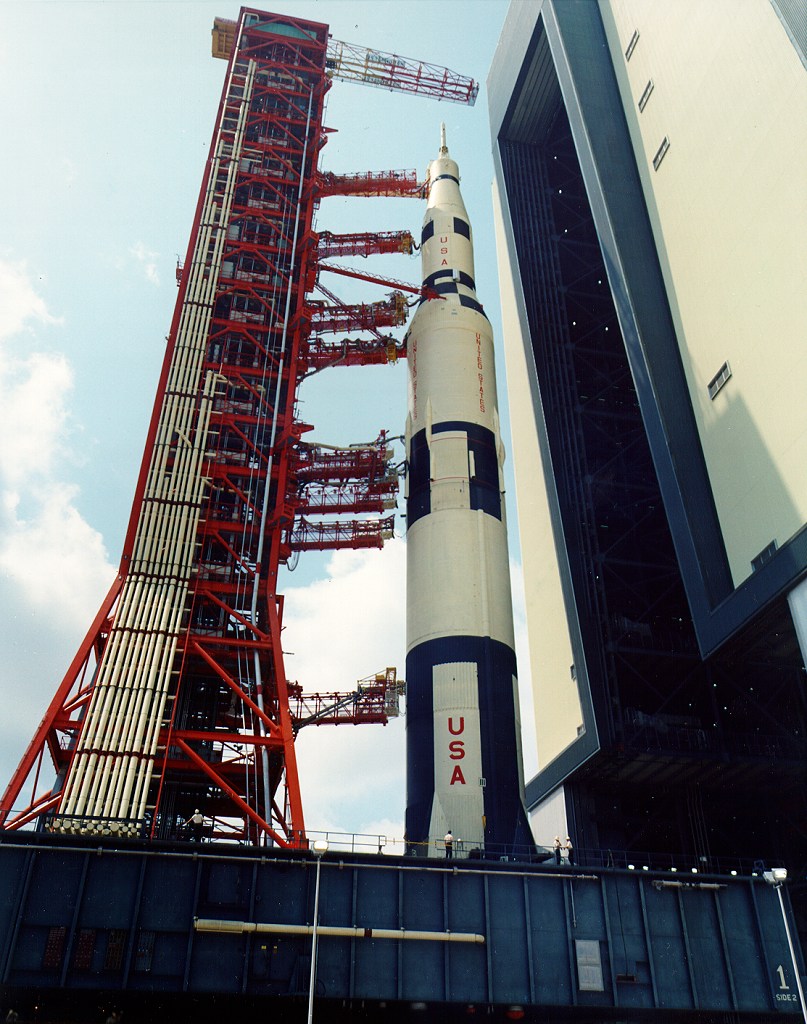
Here's another diagram with a similar Saturn IB on the pad. Although it has no serial number on its S-IB stage, it still has the SA-201 engine shrouds. However, the forward end of its S-IVB stage has a black and white roll pattern, which was present only on the SA-500F Saturn V facilities checkout vehicle; the S-IVB's forward skirt on SA-201 and SA-202 was painted entirely white.
With all the venting, the Saturn IB below must be in the final preparatory stages for launch.
Click image for a 4169x5667 pixel version of this image in a new
window.
From the second unnumbered page of the Saturn IB News
Reference (Changed September 1968). Located in the Saturn V
Collection, Dept. of
Archives/Special Collections, M. Louis Salmon Library, University of
Alabama in Huntsville.
Scan and cleanup by heroicrelics.
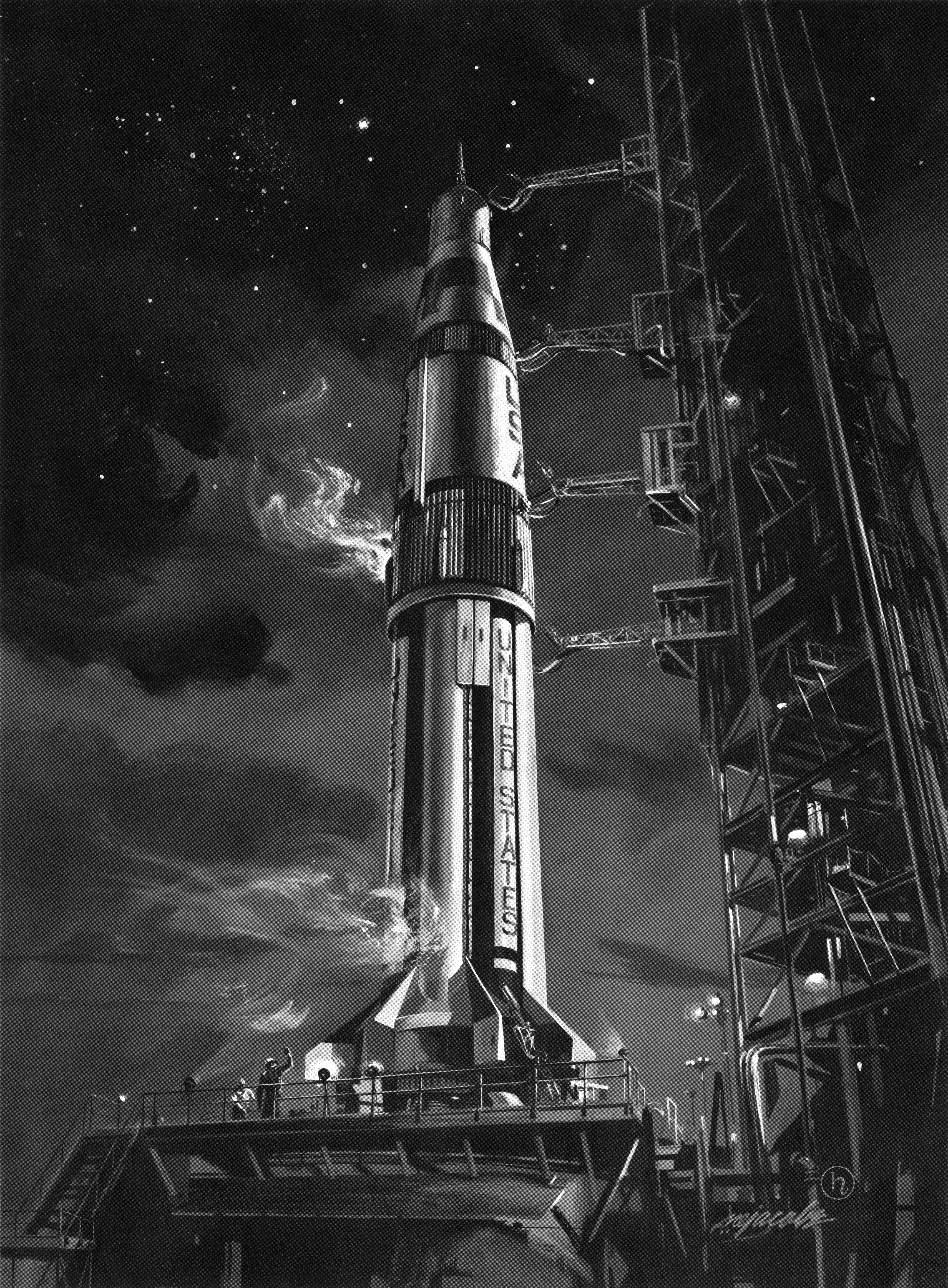
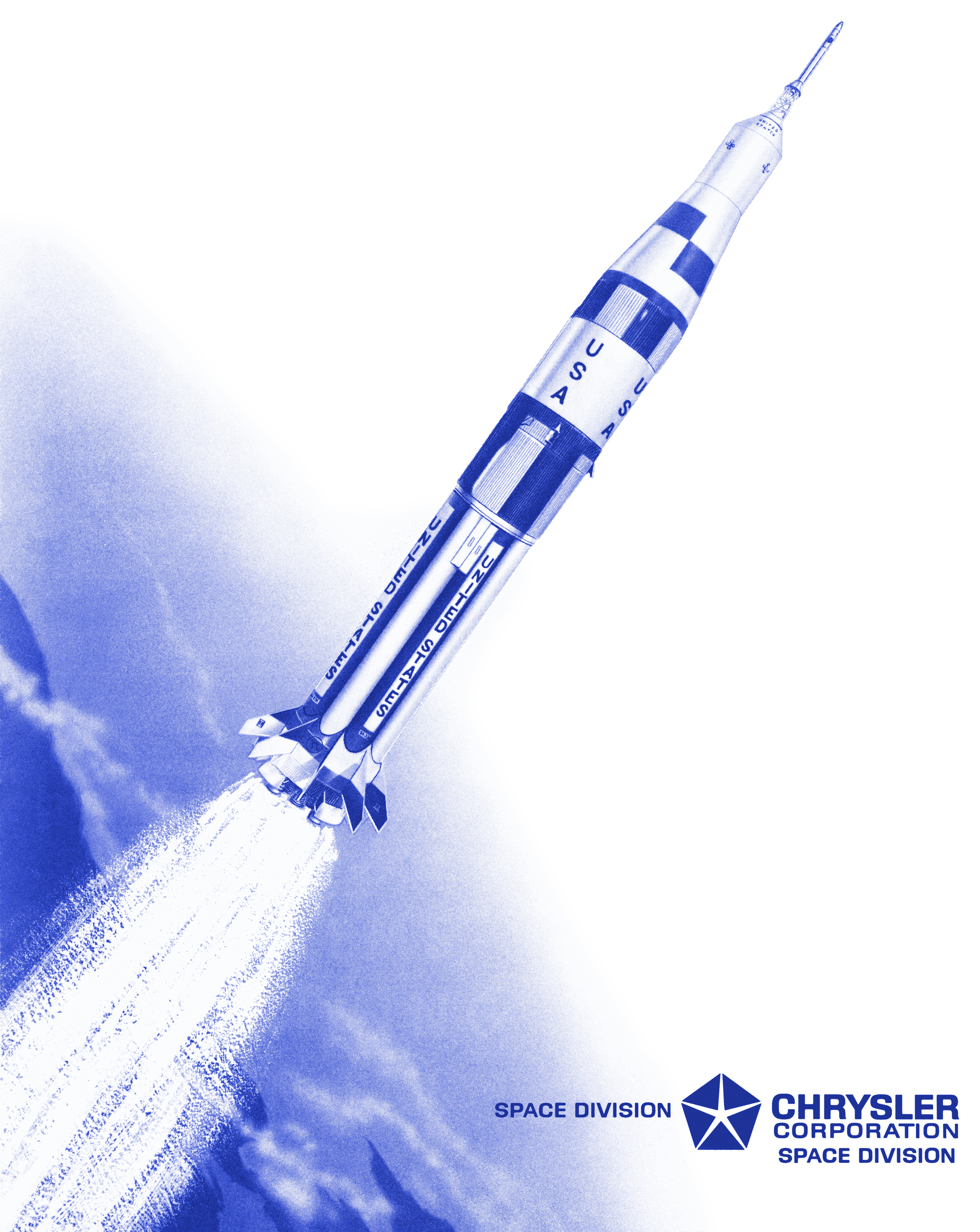
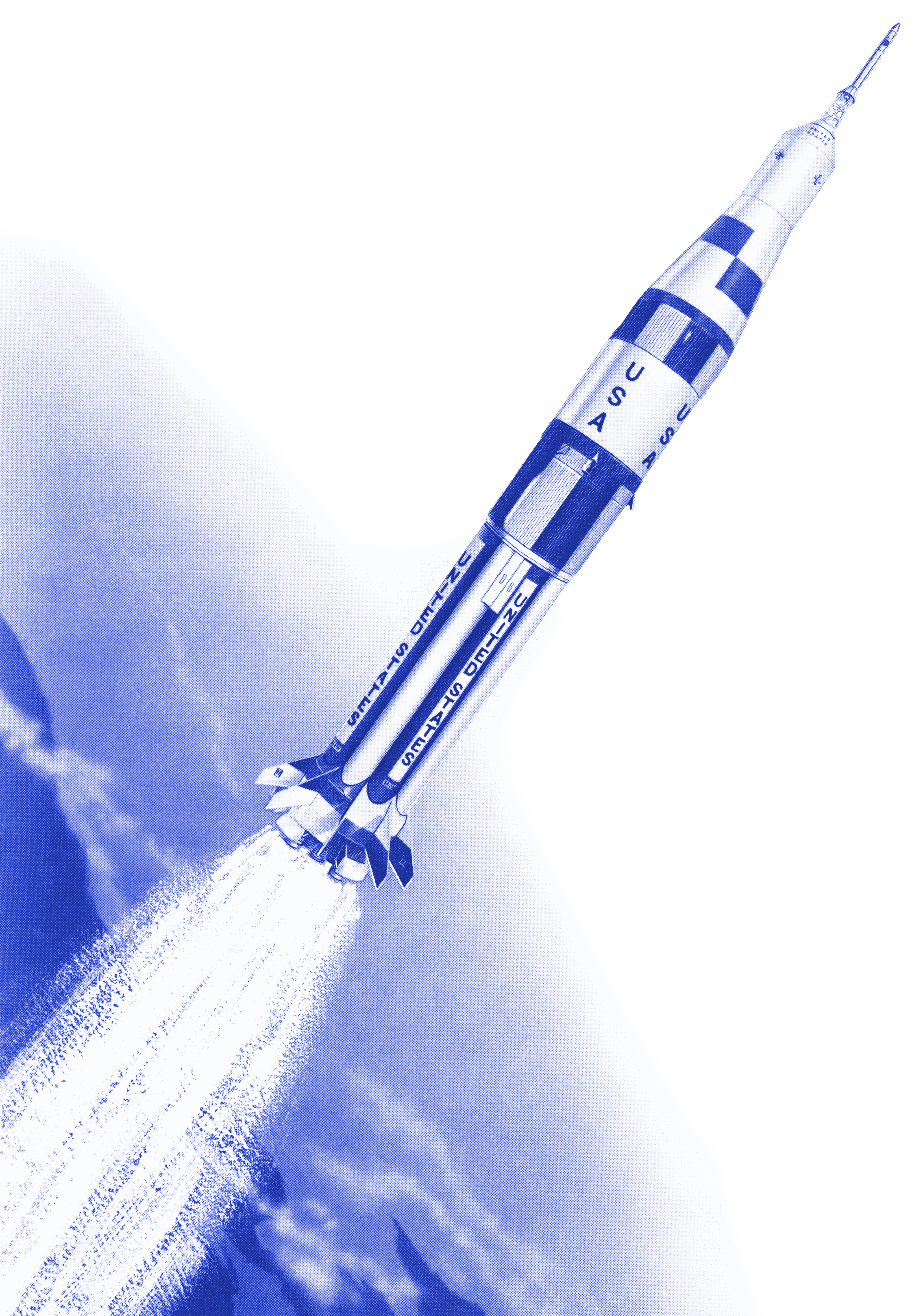
After all that pad work, it's time for an artistic rendering of a Saturn IB in flight (from the cover of the Chrysler Corporation Space Division manual Saturn IB Orientation):
Click image for a 4665x5866 pixel version of this image in a new window.
From the front cover of the Saturn IB Orientation:
Systems Training Manual. Located in the Saturn V Collection, Dept. of Archives/Special
Collections, M. Louis Salmon Library, University of Alabama in Huntsville.
Scan and reconstruction by heroicrelics.
This CCSD document was dated February of 1965, approximately one year before the first Saturn IB flight. This document depicts the same early Saturn IB concept, with engine shrouds and the SLA checkerboard pattern. It also has the roll pattern on the S-IVB forward skirt.
If you look closely at this drawing, you'll also see turbine exhaust fairings on the boattail; these were present only on SA-201 and SA-202, the first two Saturn IB vehicles manufactured. (Oddly, the two on-pad diagrams above lack the turbine exhaust fairings.)
Here's the same image, but with only the IB in flight (i.e., without the CCSD branding):
Click image for a 4116x5866 pixel version of this image in a new window.
From the front cover of the Saturn IB Orientation:
Systems Training Manual. Located in the Saturn V Collection, Dept. of Archives/Special
Collections, M. Louis Salmon Library, University of Alabama in Huntsville.
Scan and reconstruction by heroicrelics.
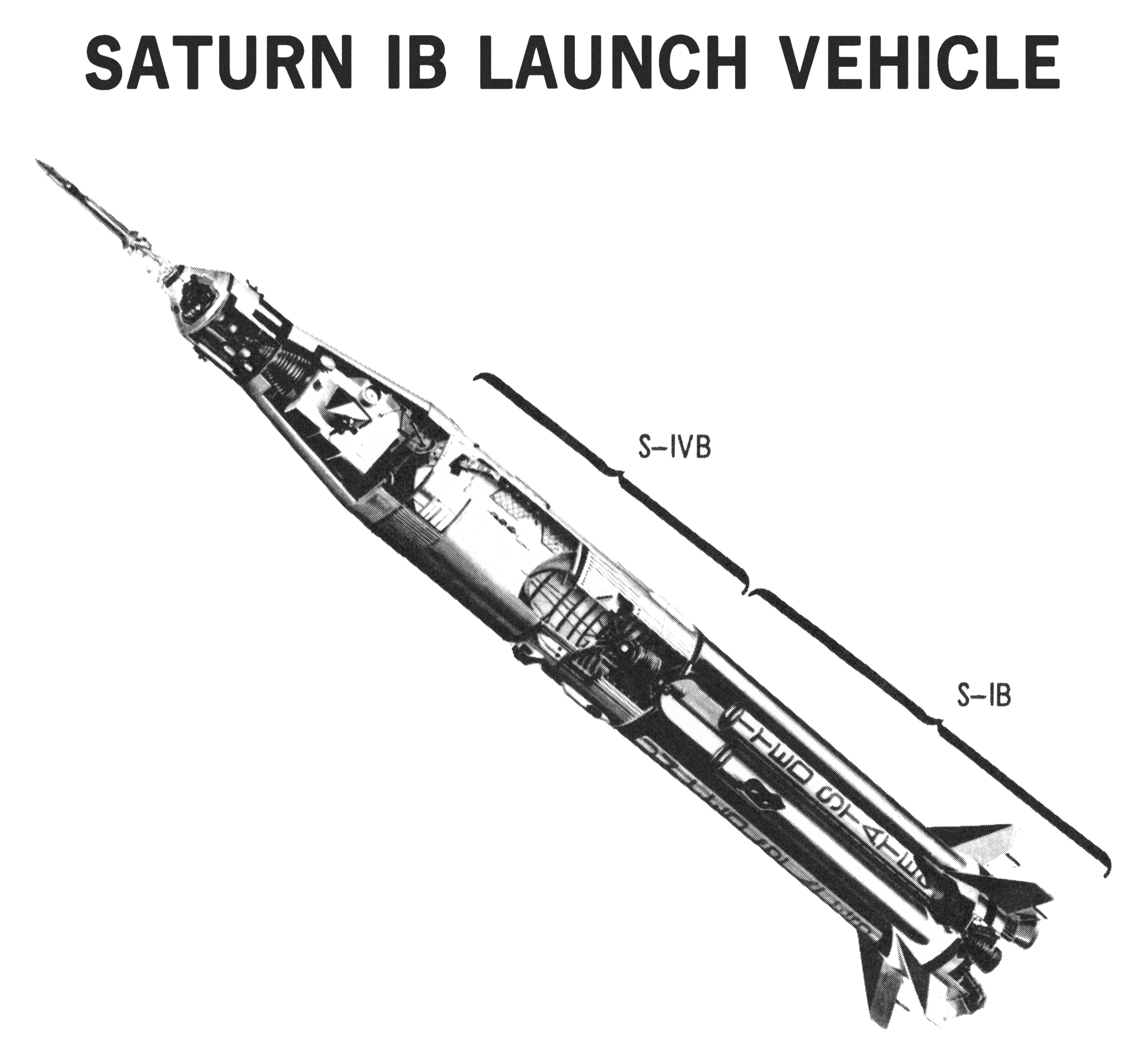
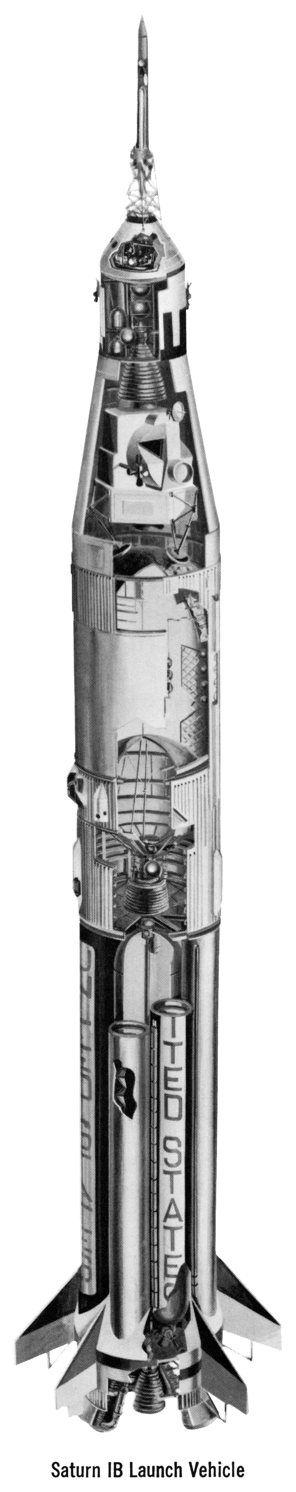
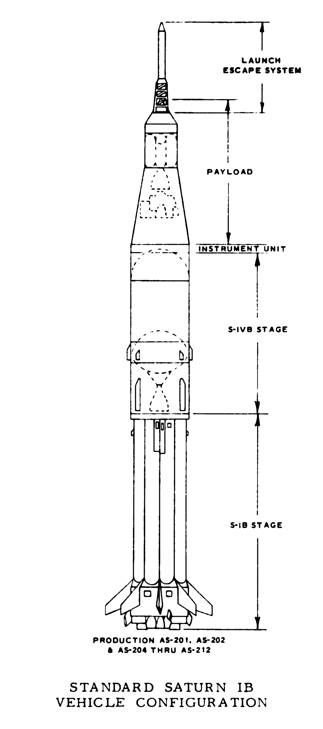
Saturn IB Launch Vehicle
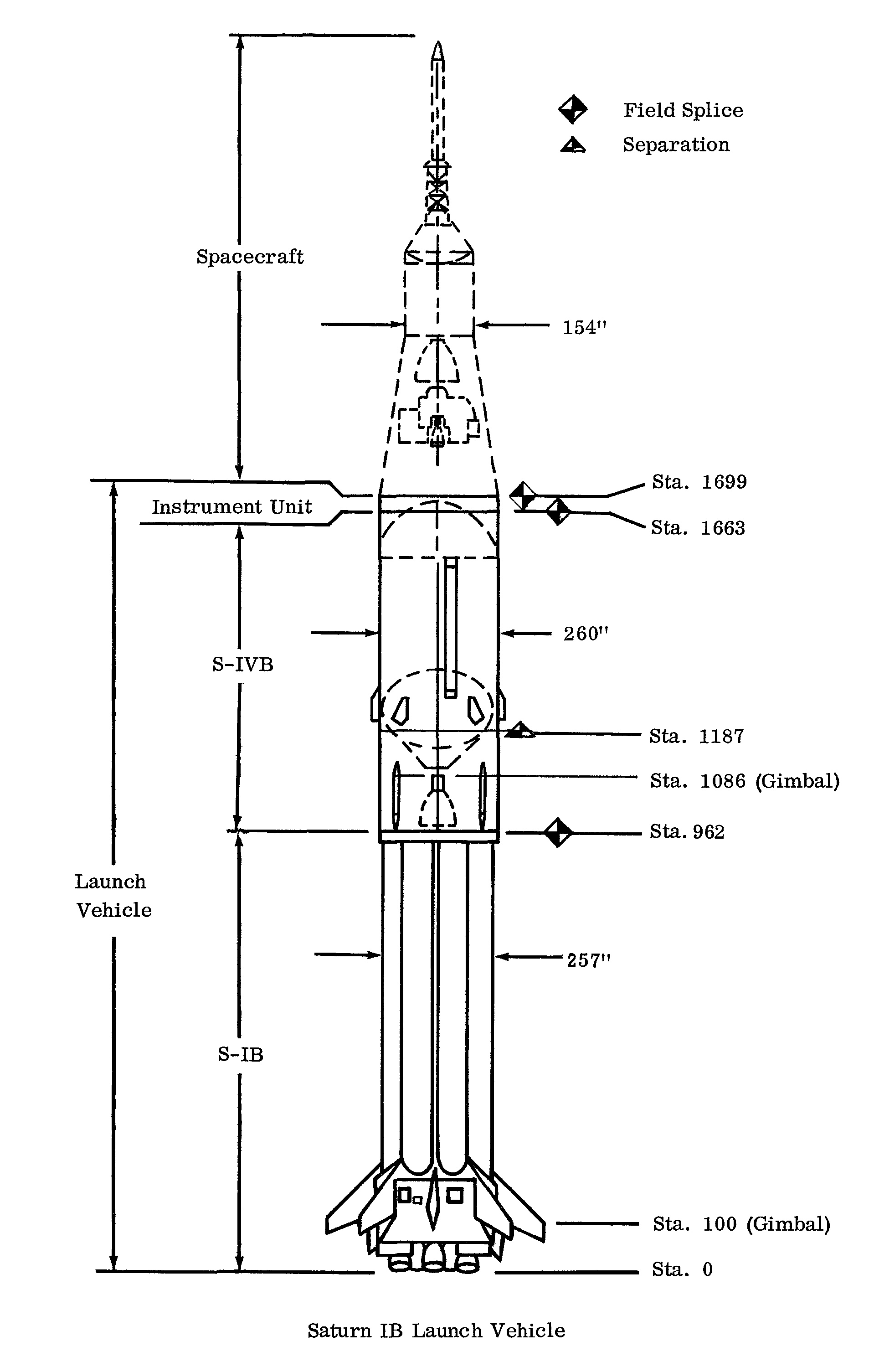
This diagram identifies each of the stages of the Saturn IB launch vehicle, with the S-IVB and S-IB stages called out:
Click image for a 3314x3076 pixel version of this image in a new window.
Adapted from page 28 of the S-IVB Saturn High
Energy Upper Stage and its Development (Douglas Paper No. 4040),
located in the Saturn V collection, Dept. of Archives/Special
Collections, M. Louis Salmon Library, University of Alabama in
Huntsville.
Scan and adaptation by heroicrelics.
Another fairly early diagram, it depicts the SA-201 engine shrouds and has also a full Apollo spacecraft (a Command/Service Module plus a Lunar Module). While the Saturn IB was originally intended to test the full Apollo spacecraft in Earth orbit, the increasing weight of the CSM and LM forced NASA to change its plans, first to launch a CSM with only an LM ascent stage on the Saturn IB, and then to launch the CSM and LM on separate launch vehicles. (In the end, the original Saturn IB mission of simultaneously, testing both the CSM and LM in Earth orbit, was flown on a Saturn V, on Apollo 9).
Click image for a 1020x5130 pixel version of this image in a new
window.
From page 2-1 of the Saturn IB News
Reference (Changed September 1968). Located in the Saturn V
Collection, Dept. of
Archives/Special Collections, M. Louis Salmon Library, University of
Alabama in Huntsville.
Scan and cleanup by heroicrelics.
Saturn IB CSM and LM Configurations
A number of different Saturn IB configurations were initially envisioned. The basic configuration was to launch a CSM/LM into Earth orbit. As the weight of the full spacecraft increased and eventually outgrew the Saturn IB's capability, diagrams were updated to show only the CSM and LM ascent stage. The Saturn IB would also be called up to launch only the LM (without a CSM). Another configuration had no payload whatsoever: an aerodynamic nose cone was added directly to the top of the S-IVB stage; the mission was to investigate the way liquid hydrogen behaved in zero G, as a precursor to restarting an S-IVB stage for the trans-lunar injection burn. Another configuration envisioned a three-stage Saturn IB, using a Centaur upper stage.
In the end, only three configurations actually flew:
- The familiar Saturn IB-with-CSM configuration:
- AS-201, an unmanned mission, with CM-009, the first production Command Module flown on a Saturn;
- AS-202, an unmanned mission;
- AS-205 (Apollo 7);
- AS-206 (SL-2, the first manned Skylab mission);
- AS-207 (SL-3, the second manned Skylab mission);
- AS-208 (SL-4, the third manned Skylab mission);
- AS-210 (Apollo-Soyuz Test Project (ASTP));
- AS-203, which flew with no payload (simply a nosecone), to test the effects of zero G on the liquid hydrogen in the S-IVB fuel tank.
- AS-204, which flew with only an LM, with a different type of nosecone in place of the CSM. This mission flew LM-1 in an Earth-orbit mission.
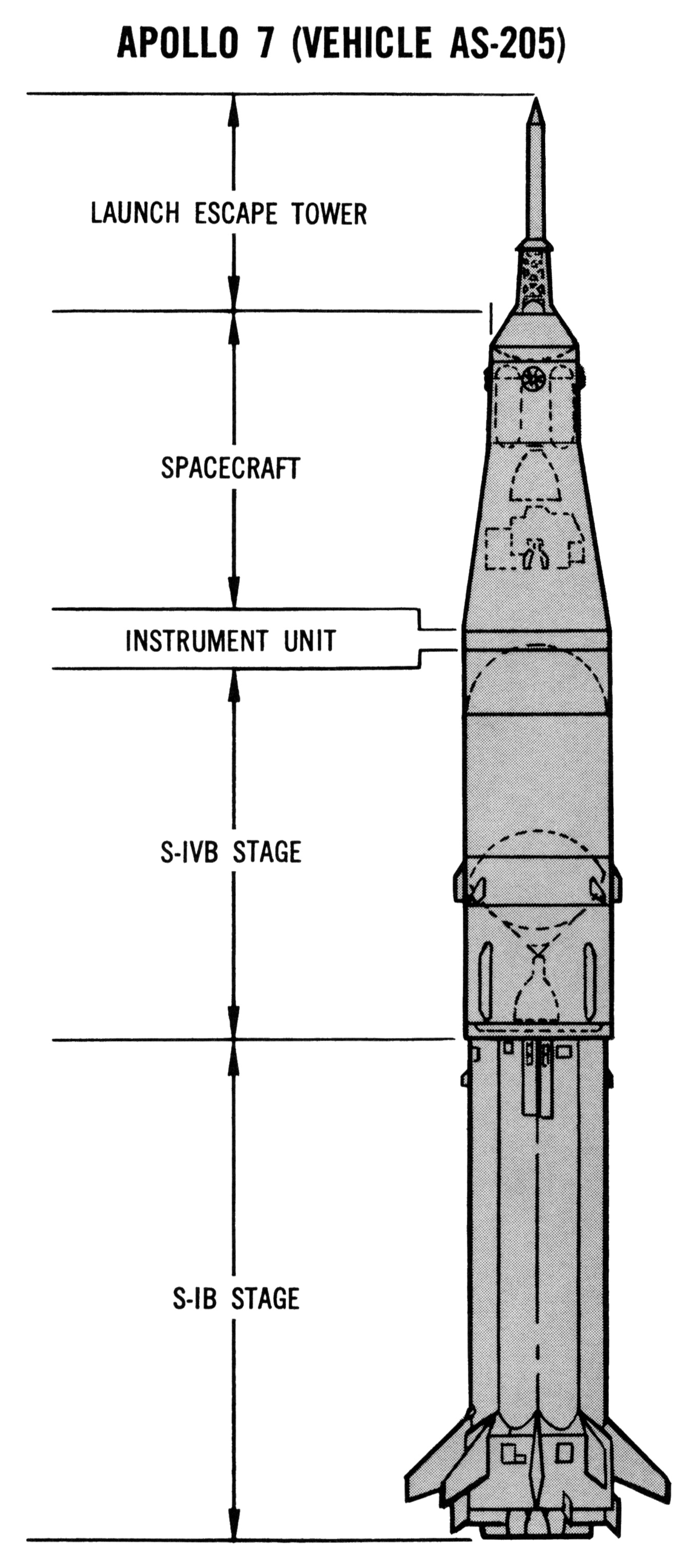
This set of diagrams, more or less, depicts each of the configurations which actually flew.
The Apollo 7 configuration is the basic configuration which flew all of the Saturn IB missions other than AS-203 and AS-204. Differences from actual flight configurations include a Lunar Module ascent stage (the Saturn IB never launched any part of an LM with a CSM), turbine exhaust fairings (which flew only on AS-201 and AS-202), and engine fairings (only AS-201).
The AS-204 diagram is fairly accurate, although it seems to have at least two turbine exhaust fairings and engine shrouds. The first stage of the AS-203 vehicle appears to have been taken directly from the AS-205 diagram (or some common ancestor), and so has the same problems. I'm not certain what the round "dot" on the top of the nose cone is. Note that the AS-203 nose cone appears to be the same as that envisioned for the Saturn IB/Centaur.
Click image for a 1358x3062 pixel version of this image in a new window.
Adapted from the fourth unnumbered page at the beginning of section 2 of
the Saturn IB News
Reference (Changed September 1968). Located in the Saturn V
Collection, Dept. of
Archives/Special Collections, M. Louis Salmon Library, University of
Alabama in Huntsville.
Scan, cleanup, and adaptation by heroicrelics.
Click image for a 1080x2942 pixel version of this image in a new window.
Adapted from the third unnumbered page at the beginning of section 2 of the
Saturn IB News
Reference (Changed September 1968). Located in the Saturn V
Collection, Dept. of
Archives/Special Collections, M. Louis Salmon Library, University of
Alabama in Huntsville.
Scan, cleanup, and adaptation by heroicrelics.
Click image for a 1313x2996 pixel version of this image in a new window.
Adapted from the first unnumbered page at the beginning of section 2 of the
Saturn IB News
Reference (Changed September 1968). Located in the Saturn V
Collection, Dept. of
Archives/Special Collections, M. Louis Salmon Library, University of
Alabama in Huntsville.
Scan, cleanup, and adaptation by heroicrelics.
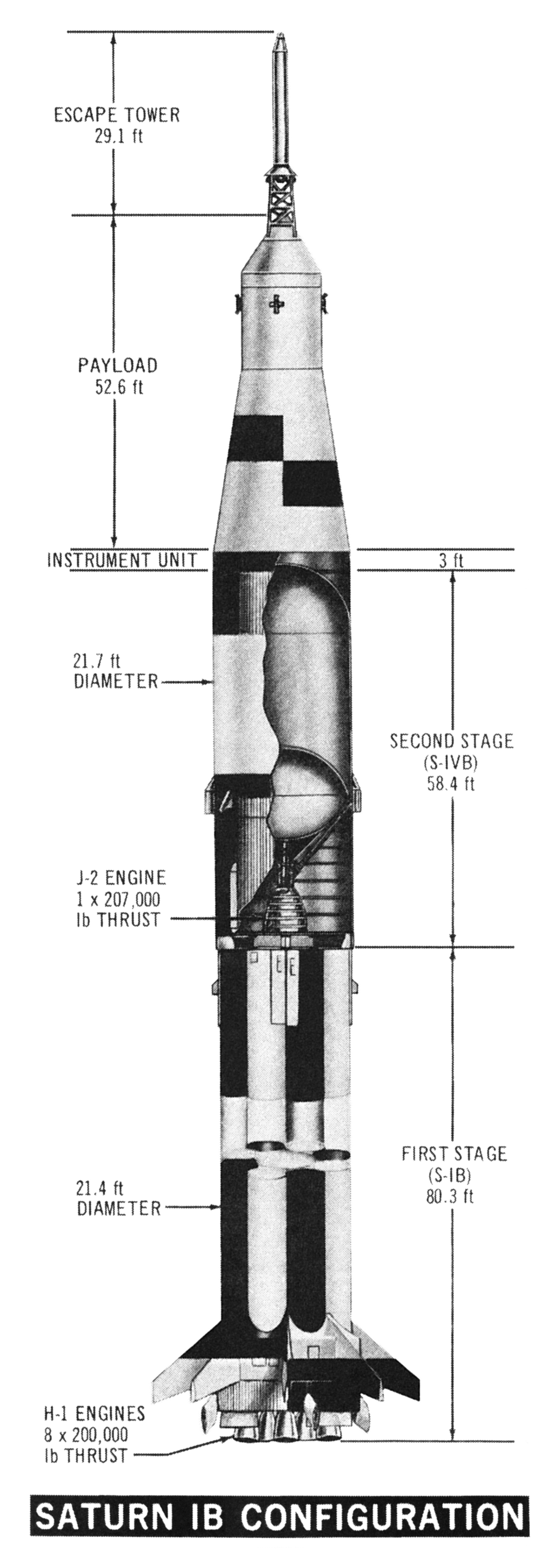
Saturn IB, CSM Configuration
Taken from the same Chrysler Corporation Space Division Saturn IB Orientation manual as the blue, in-flight drawing above, this cut-away CSM configuration diagram reflects an early configuration, with engine fairings, turbine exhaust fairings, and a checkerboard pattern on the SLA.
This diagram calls out each stage, along with the stage particulars:
- The first stage (S-IB), at 80.3 feet in length and 21.4 feet in diameter, with 8 H-1 rocket engines of 200,000 lb thrust each. (On later missions, H-1 thrust was uprated to 205,000 lbs.)
- The second stage (S-IVB), at 58.4 feet in length and 21.7 feet in diameter, with a single J-2 rocket engine of 207,000 lb thrust.
- The instrument unit, at 3 feet high.
- The payload, or Apollo spacecraft, at 52.6 feet tall. While the "Apollo spacecraft" is generally cited to include the SLA (because the Lunar Module was inside it), it also usually includes the Launch Escape Tower.
- The Launch Escape Tower, at 29.1 feet.
If one does the math, the Saturn IB in this diagram comes to 223.4 feet tall, close to the "official" height of 224 feet.
Click image for a 1870x5247 pixel version of this image in a new window.
Adapted from page 24 of the Saturn IB Orientation:
Systems Training Manual. Located in the Saturn V Collection, Dept. of Archives/Special
Collections, M. Louis Salmon Library, University of Alabama in
Huntsville.
Scan and adaptation by heroicrelics.
January 1967 (the date of this diagram; nearly eleven months after AS-201 flew—without an LM; after AS-203 flew; and as the AS-204/Apollo 1 mission was preparing to fly) would seem to be late enough to reflect an accurate configuration, but instead this diagram shows the same basic concepts (Lunar Module ascent stage, turbine exhaust fairings, and engine shrouds) as the February 1964 diagram below:
Click image for a 1100x2483 pixel version of this image in a new window.
Adapted from page II-5 (page 22 in the PDF) of Evaluation of AS-203 Low
Gravity Orbital Experiment.
Extraction, cleanup, and adaptation by heroicrelics.
This diagram, dating back to February 1964, depicts the Saturn IB with a CSM, a Lunar Module ascent stage, and engine shrouds:
Click image for a 1918x3010 pixel version of this image in a new window.
Taken from page 12-4 (page 344 in the PDF) of Apollo
Systems Description, Volume 2 - Saturn Launch Vehicles.
Extraction and reconstruction by heroicrelics.
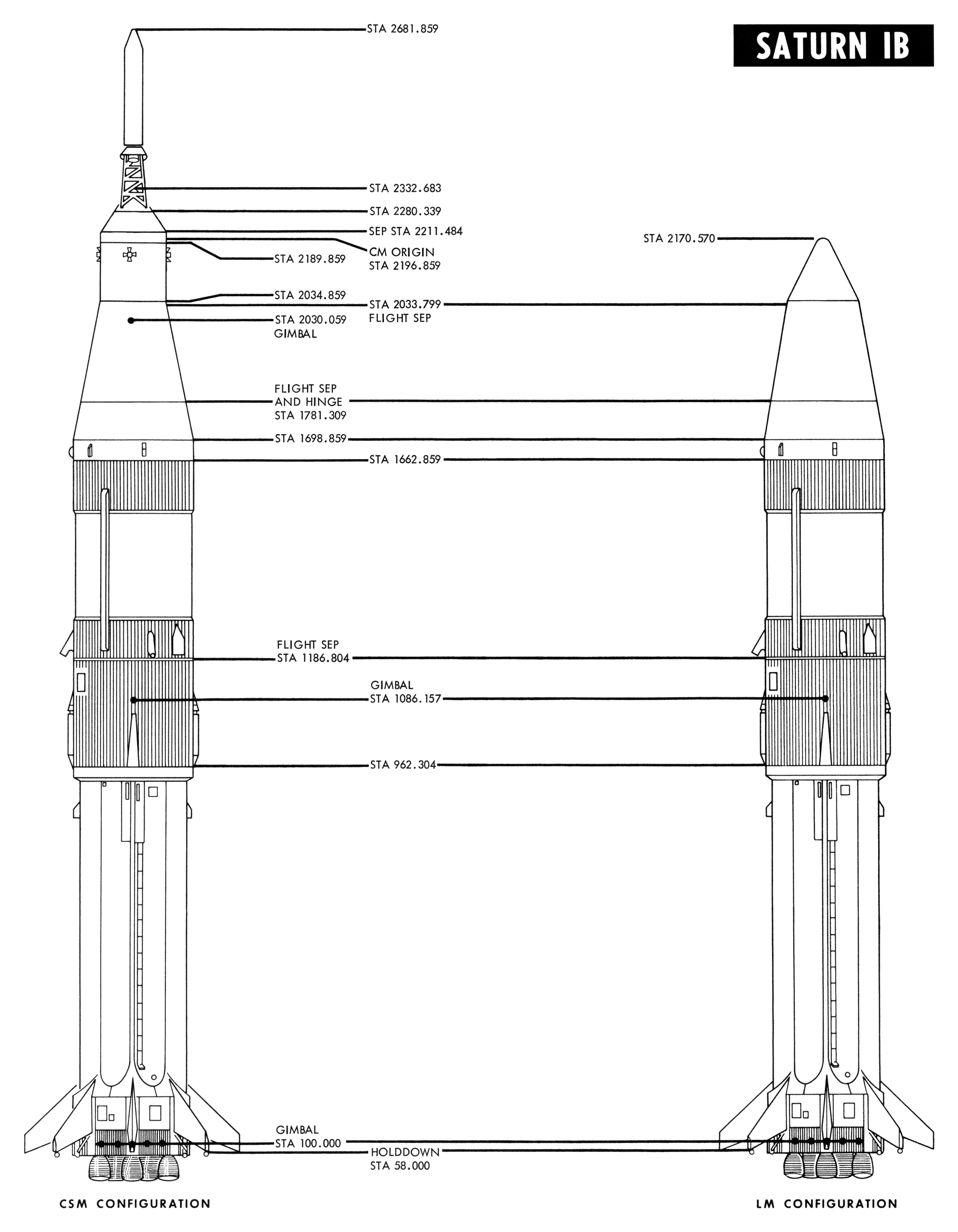
The following diagram shows the standard CSM configuration as well as the SA-204 (LM-only) configuration:
Click image for a 3990x5133 pixel version of this image in a new window.
Adapted from page iv of the Saturn IB Flight Manual (April
15,1968), located in the Mauldin collection, Dept. of Archives/Special
Collections, M. Louis Salmon Library, University of Alabama in
Huntsville.
Scan and adaptation by heroicrelics.
This diagram, no doubt drawn by a launch vehicle (rather than spacecraft) draftsman, shows the Saturn IB with the interchangeable payload configurations which actually flew. Dated February 1968, this diagram reflects the reality that the full CSM/LM outgrew the Saturn IB's capabilities:

Click image for a 3804x5256 pixel version of this image in a new window.
From page 1 of H-1 Rocket Engine Technical Data (R-3620-1A),
located in a private collection.
Scan and cleanup by heroicrelics.
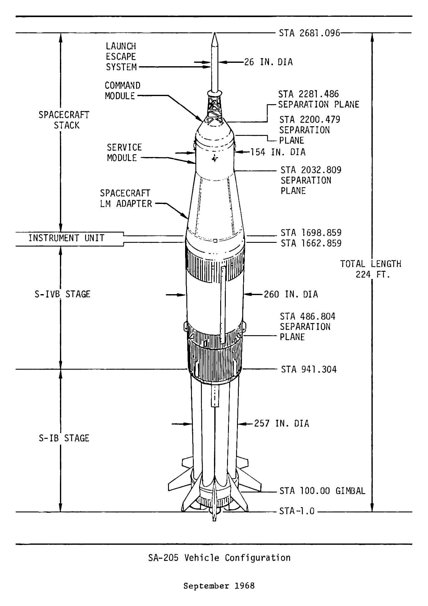
Dated September 1968, the following diagram shows the Saturn IB which launched Apollo 7:
Click image for a 1378x1949 pixel version of this image in a new window.
Taken from the page 2-12 (p. 32 in the PDF) of S-IVB-205 Stage Flight Test
Plan.
Extraction and cleanup by heroicrelics.
These last four diagrams also show the MSFC station numbers. Station numbers are measured in inches, with station 100 being defined as the engine gimbal plane (I assume this convention started with the Jupiter missile, the first ABMA missile with a gimballing engine). Assigning station 100 to the engine gimbal plane became awkward in later boosters, giving rise to negative station numbers (the H-1 engine apparently gimballed 101.0 to 101.785 inches forward of its exit plane).
The highest station number is 2681.859 (or perhaps 2681.096), a bit over 223 feet 5 inches. Compensating for the negative station number in the last diagram, this puts the Saturn IB's height at just under 223 feet, 7 inches. The Saturn IB News Reference quotes the height at 224 feet, which is pretty close. (Although the H-1 engines were apparently about 1 3/4" inches shorter in February 1964, as that diagram shows the engine exit plane at Sta. 0.)
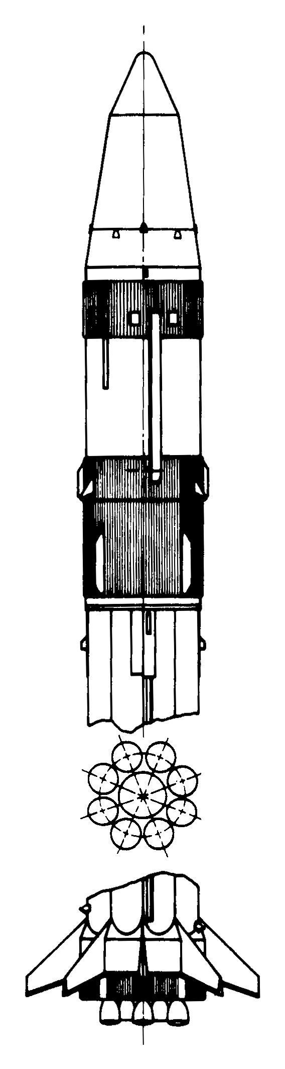
Saturn IB, LM Configuration
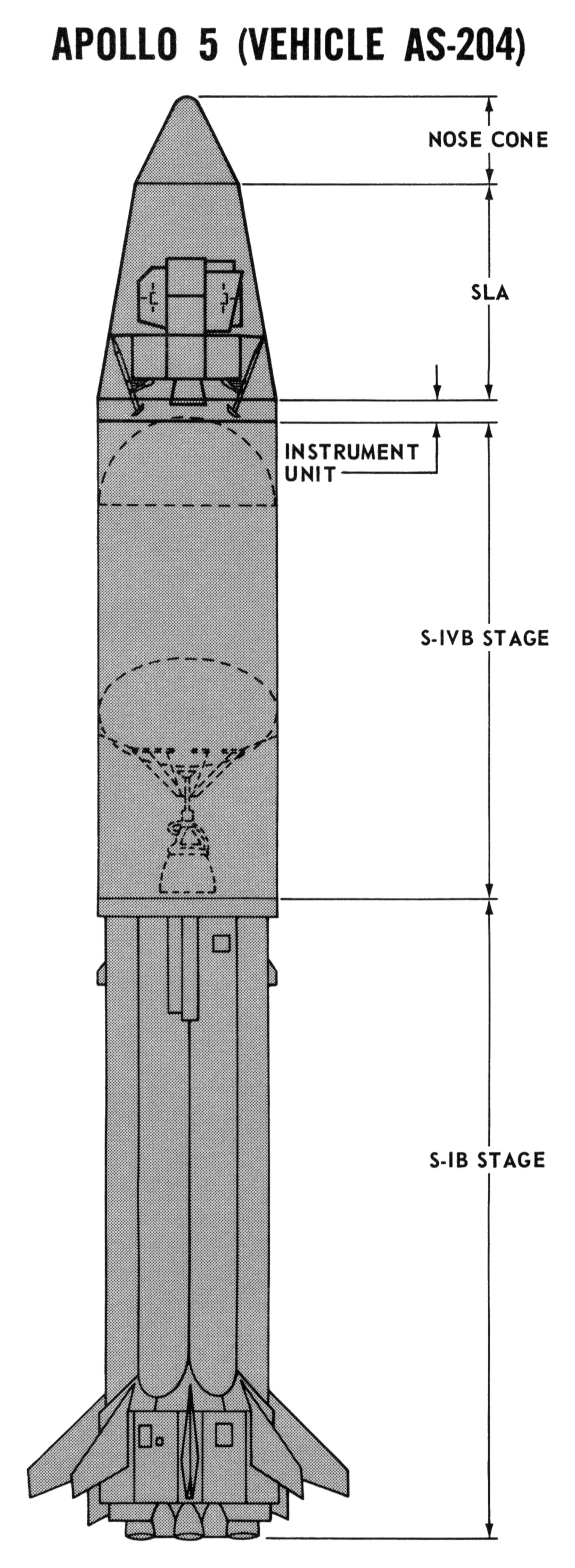
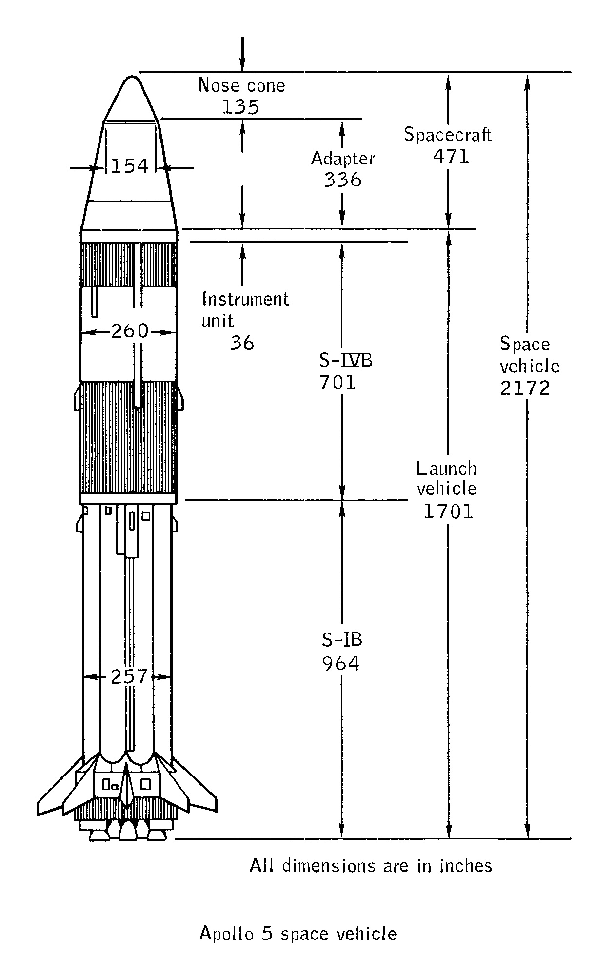
Since I found the diagrams above showing both the CSM and SA-204 configurations, I'll defer the SA-203 diagrams for the time being and transition directly to the SA-204/LM-1 (Apollo 5) diagrams.
The Saturn IB launch vehicle is the same as the CSM configuration (a point well-made with the dual-headed diagram above) and the S-IVB stage is topped with a standard Spacecraft-Lunar Module Adapter (SLA). However, rather than flying a CSM (which would have been too heavy) or a boilerplate (as on the last five Saturn I Block II flights), a simple nosecone covered the SLA.
Noteworthy in this diagram is the depiction of the S-IB's clustered propellant tank configuration: At the center is a 105" LOX container (based on the Jupiter missile tankage), surrounded by four 70" LOX containers alternating with four 70" RP-1 containers (derived from Redstone missile tankage).
Click image for a 568x2126 pixel version of this image in a new window.
Taken from the page 245 (page 270 in the PDF) of Results
of the Fourth Saturn IB Launch Vehicle Test Flight AS-204.
Extraction and cleanup by heroicrelics.
This diagram calls out each stage, along with the stage particulars:
- The first stage (S-IB), at 964" (80 feet, 4 inches) tall and 257" (21 feet, 5 inches) in diameter.
- The second stage (S-IVB), at 701" (58 feet, 5inches) tall and 260" (21 feet, 8 inches) in diameter.
- The instrument unit, at 36" (3 feet) tall.
-
The spacecraft, at 471" (39 feet, 3 inches) tall, which consisted of
- The adapter (a standard SLA), at 336" (28 feet exactly) tall.
- A nose cone, at 135" (11 feet, 3 inches) tall.
The entire "space vehicle" weighs in at 2,172" (181 feet exactly) tall.
Click image for a 1222x2008 pixel version of this image in a new window.
Taken from the page 13-2 (page 313 in the PDF) of Apollo
5 Mission Report.
Extraction and cleanup by heroicrelics.
This diagram shows the same basic information as the one above, but contains more detailed information, showing the ullage and retro motors, the S-IB's 8 H-1 engines, and the S-IVB's J-2 engine.
This may well be the only diagram I've seen with metric station numbers. I usually think of the U.S. push for metrication as occurring in the early 1970s, but a bit of research shows that the National Bureau of Standards started the push as early as 1964. In any case, the metrication took place at the expense of some Imperial precision: Most diagrams with station numbers have units out to the thousandths of an inch, whereas here the measurements have been rounded to the nearest inch.

Click image for a 2154x2465 pixel version of this image in a new window.
Taken from the page 299 (page 324 in the PDF) of Results
of the Fourth Saturn IB Launch Vehicle Test Flight AS-204.
Extraction and reconstruction by heroicrelics.
At first glance, it appears that the measurements on this diagram conflict with the one above (the top of the S-IB at Sta 962, rather than an S-IB height of 964" as shown above, and the overall height being 2,170", rather than 2,172" above). However, as with one of the CSM diagrams above, we see here that the bottom of the launch vehicle is at Sta. -1.785, so 1.785" must be added to the station numbers in this diagram.
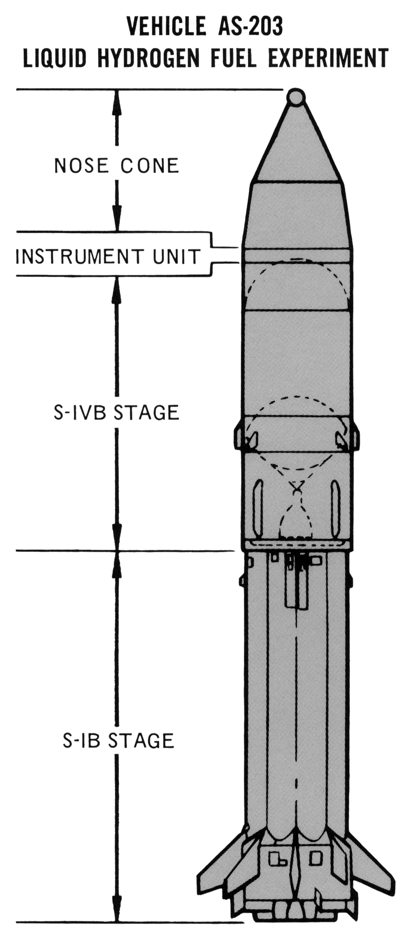
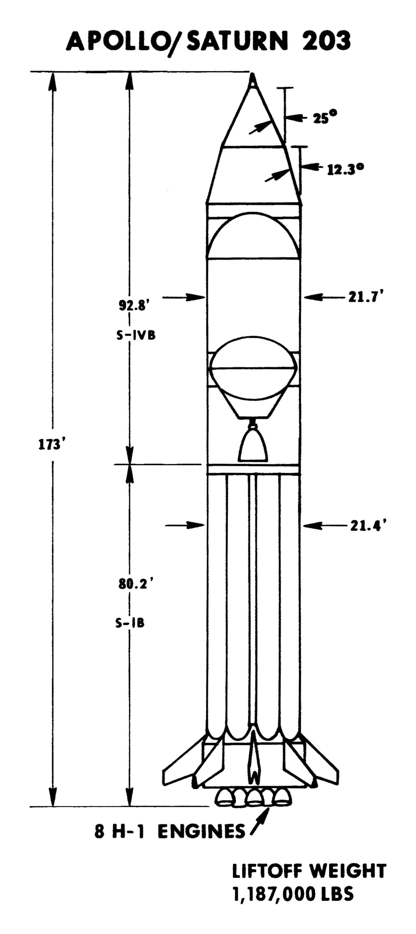
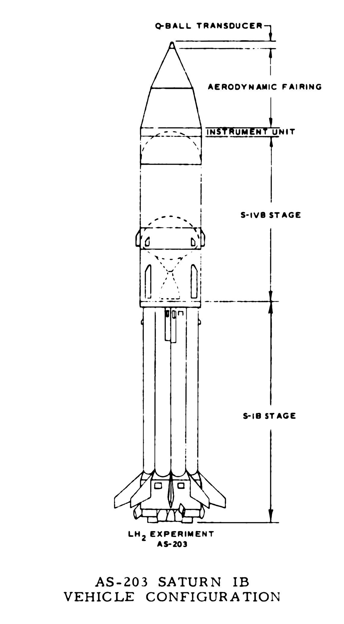
Saturn IB, Liquid Hydrogen Experiment Configuration
Diagrams of SA-203 are harder to come by, but I have a few.
This diagram shows SA-203, the liquid hydrogen experiment. Without the SLA, CSM, and LES, it's a good deal shorter than the standard Saturn IB, at 173 feet. This diagram also gives some particulars about the aerodynamic nosecone.
Click image for a 1393x3126 pixel version of this image in a new window.
Taken from the unnumbered page between pages 13 and 14 (page 15 in the PDF) of
Second Unmanned
Apollo Mission, a Unique Study (SA-203 Press Kit).
Extraction and reconstruction by heroicrelics.
January 1967, the date of this diagram, would seem to be late enough to reflect an accurate launch vehicle configuration, but again it shows the same AS-201-type protuberances about which I've been complaining in most of this page:
Click image for a 1142x2072 pixel version of this image in a new window.
Adapted from page II-5 (page 22 in the PDF) of Evaluation of AS-203 Low
Gravity Orbital Experiment.
Extraction, cleanup, and adaptation by heroicrelics.
The diagram above notes that, even with the aerodynamic shroud, the launch vehicle still had a Q-ball, used to determine the vehicle's angle of attack. Perhaps the round dot on the AS-203 higher up on the page is supposed to represent the Q-ball?
Saturn IB Cutaway
A cutaway diagram with many components called out:

Click image for a 2183x5665 pixel version of this image in a new window.
From page 1-2 of the Saturn IB Flight Manual (MSFC-MAN-205), dated
April 15, 1968. Located in the Mauldin collection, Dept. of Archives/Special
Collections, M. Louis Salmon Library, University of Alabama in
Huntsville.
Scan and reconstruction by heroicrelics.
The callouts on this diagram include
- Boost Protective Cover
- Spacecraft LM Adapter
- LH2 Tank Forward Dome
- S-IVB Stage
- Common Bulkhead
- APS Module
- Fuel Feed Duct
- Retrorocket
- S-IB Stage
- Center LOX Tank
- Antislosh Baffles
- Propellant Suction Line
- Hydraulic Actuator
- Heat Shield
- Q-Ball
- Launch Escape Motor
- Command Module
- RCS Engines
- Service Module
- Instrument Unit Umbilical
- Instrument Unit
- S-IVB Forward Umbilical
- Auxiliary Tunnel
- Helium Storage Sphere
- Main Tunnel
- Aft Dome
- S-IVB Aft Umbilical
- Ullage Rocket
- Aft Interstage
- J-2 Engine
- Spider Beam
- S-IB Forward Umbilical
- Antenna Panel
- Outer LOX Tank
- Fuel Tank
- S-IB Aft Umbilical
- Fin
- Support and Holddown Fitting
- H-1 Engine