
S-IVB (Saturn IB) Overview
The S-IVB, the second stage of the Saturn IB rocket, was the one of the largest liquid hydrogen stages produced in the 1960s. Equipped with one J-2 rocket engine, it produced about 200,000 pounds of thrust. It was 21 feet 8 inches in diameter and 58 feet 5 inches high.
Structurally, the S-IVB stage consisted of
- An aft interstage, which mated the stage to the S-IB first stage. Although I tend to associate the interstages with the lower stage, the interstage was properly part of the S-IVB.
- A cylindrical aft skirt, to which was connected the conical thrust structure. The engine was mounted to the thrust structure, which transmitted the thrust to the aft skirt, which in turn transmitted the thrust to the propellant tank walls.
- A liquid oxygen tank and a liquid hydrogen tank. Rather than each tank having customary hemispherical bulkheads at both ends (and separated by an intertank structure, as with the S-IC), the forward end of the LOX tank and the aft end of the LH2 tank were separated by a common bulkhead. The common bulkhead consisted of two aluminum domes forming the ends of the respective propellant containers separated by honeycomb insulation; the honeycomb insulation was necessary to prevent the LH2's -423° temperature from freezing the liquid oxygen.
- A cylindrical forward skirt, attached to the forward end of the LH2 tank, which transmitted the thrust loads to the Apollo payload. Range safety and telemetry antennas were mounted on the exterior of the forward skirt, and the interior of the forward skirt had cold plates to provide environmental conditioning for various electronic equipment also located on the walls of the forward skirt.
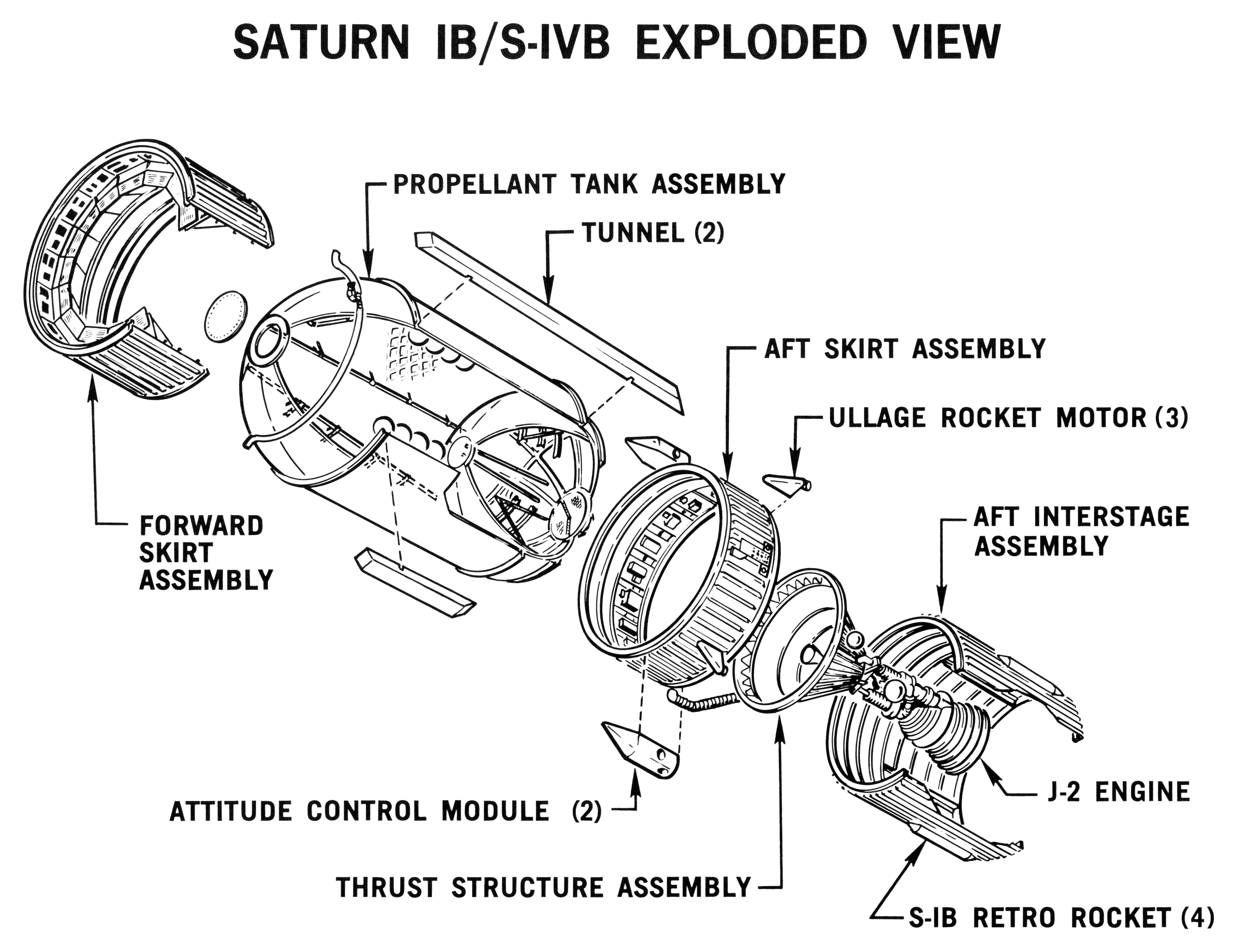
Click image for a 5351x4117 pixel version of this image in a new window.
From page 21 of the Saturn S-IVB Training Graphics: Systems
Familiarization (Revised January 1965), located in the Mauldin
collection at the Dept. of
Archives/Special Collections, M. Louis Salmon Library, University of
Alabama in Huntsville.
Scan and reconstruction by heroicrelics.org.
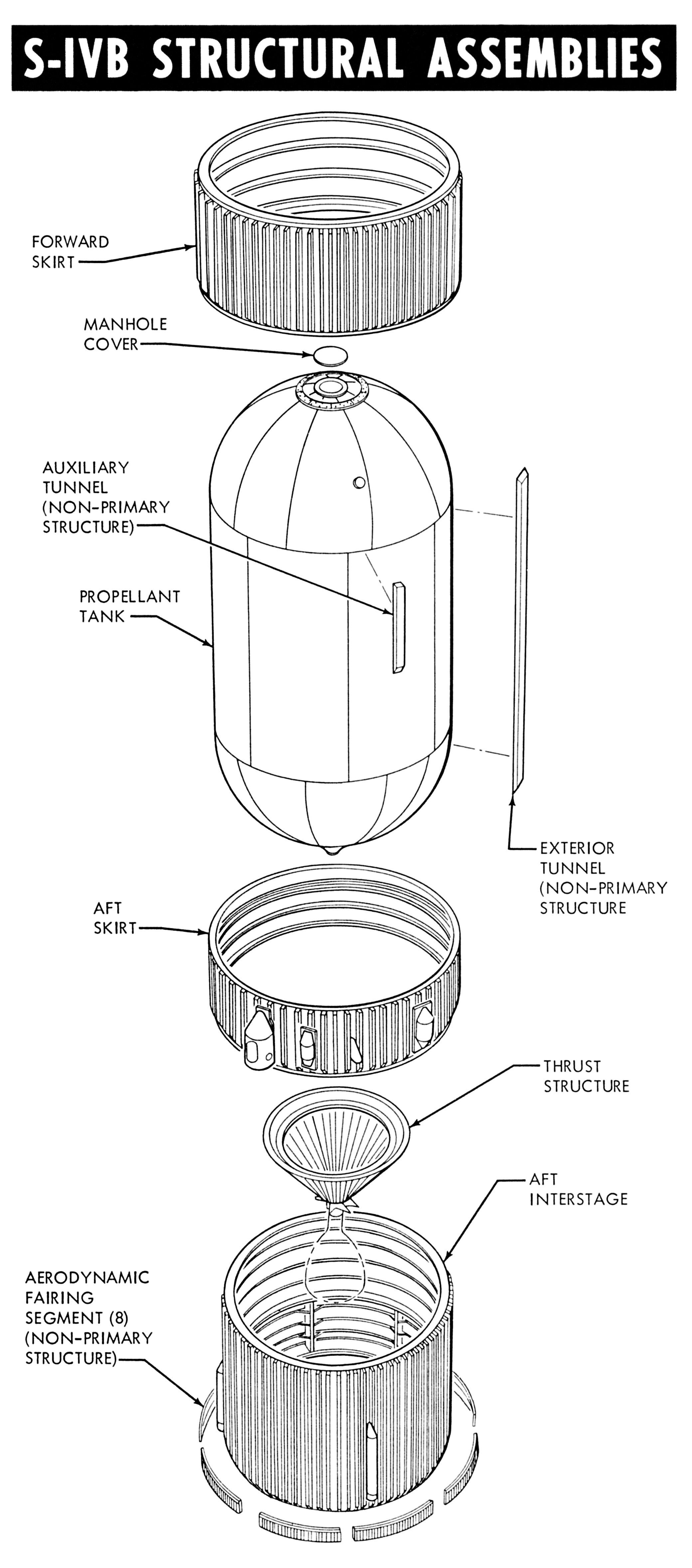
Click image for a 2080x4711 pixel version of this image in a new
window.
From page 5-7 of the Saturn S-IVB Flight Manual
(MSFC-MAN-205), located in the Mauldin collection at the Dept. of Archives/Special
Collections, M. Louis Salmon Library, University of Alabama in
Huntsville.
Scan by heroicrelics.org.
This cut-away diagram shows the major structural elements assembled into the final stage.
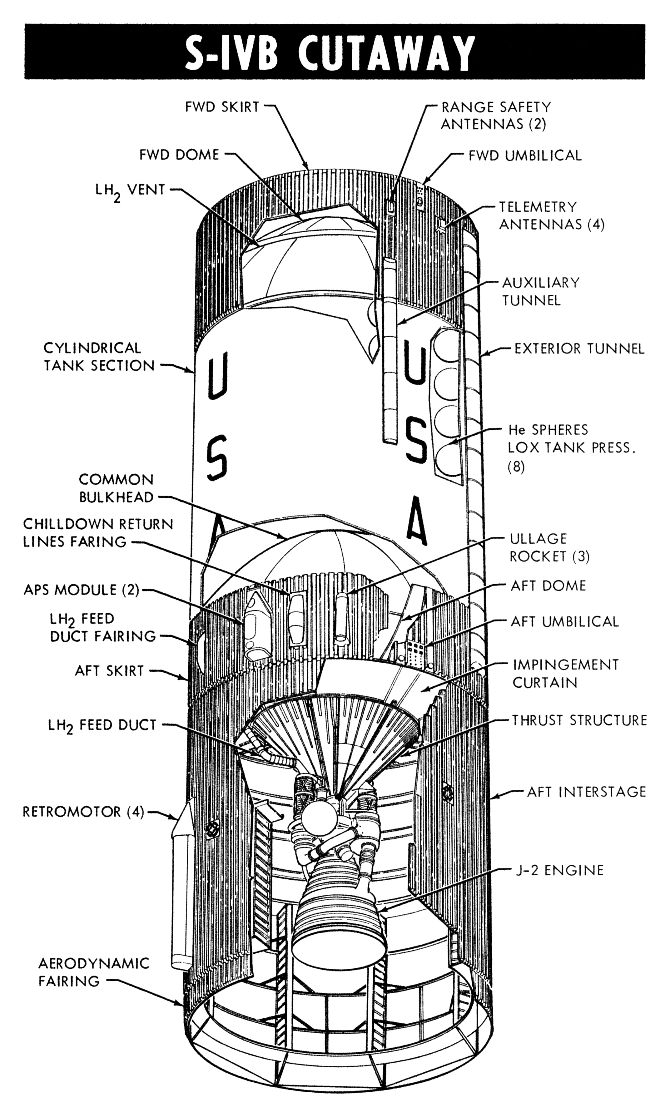
Click image for a 2145x3577 pixel version of this image in a new window.
From page 5-1 of the Saturn S-IVB Flight Manual (MSFC-MAN-205),
located in the Mauldin collection at the Dept. of Archives/Special
Collections, M. Louis Salmon Library, University of Alabama in
Huntsville.
Scan by heroicrelics.org.
This diagram calls out a number of components and features:
- Forward skirt
- Forward dome
- LH2 vent
- Cylindrical tank section
- Common bulkhead
- Chilldown return lines fairing
- APS Module (2)
- LH2 feed duct fairing
- Aft skirt
- LH2 feed duct
- Retromotor (4)
- Aerodynamic fairing
- Range safety antennas (2)
- Forward umbilical
- Telemetry antennas (4)
- Auxiliary tunnel
- Exterior tunnel
- Helium spheres, LOX tank pressurization (8)
- Ullage rocket (3)
- Aft dome
- Aft umbilical
- Impingement curtain
- Thrust structure
- Aft interstage
- J-2 engine
Dated September 1968, the following diagram shows the S-IVB configuration which launched Apollo 7:
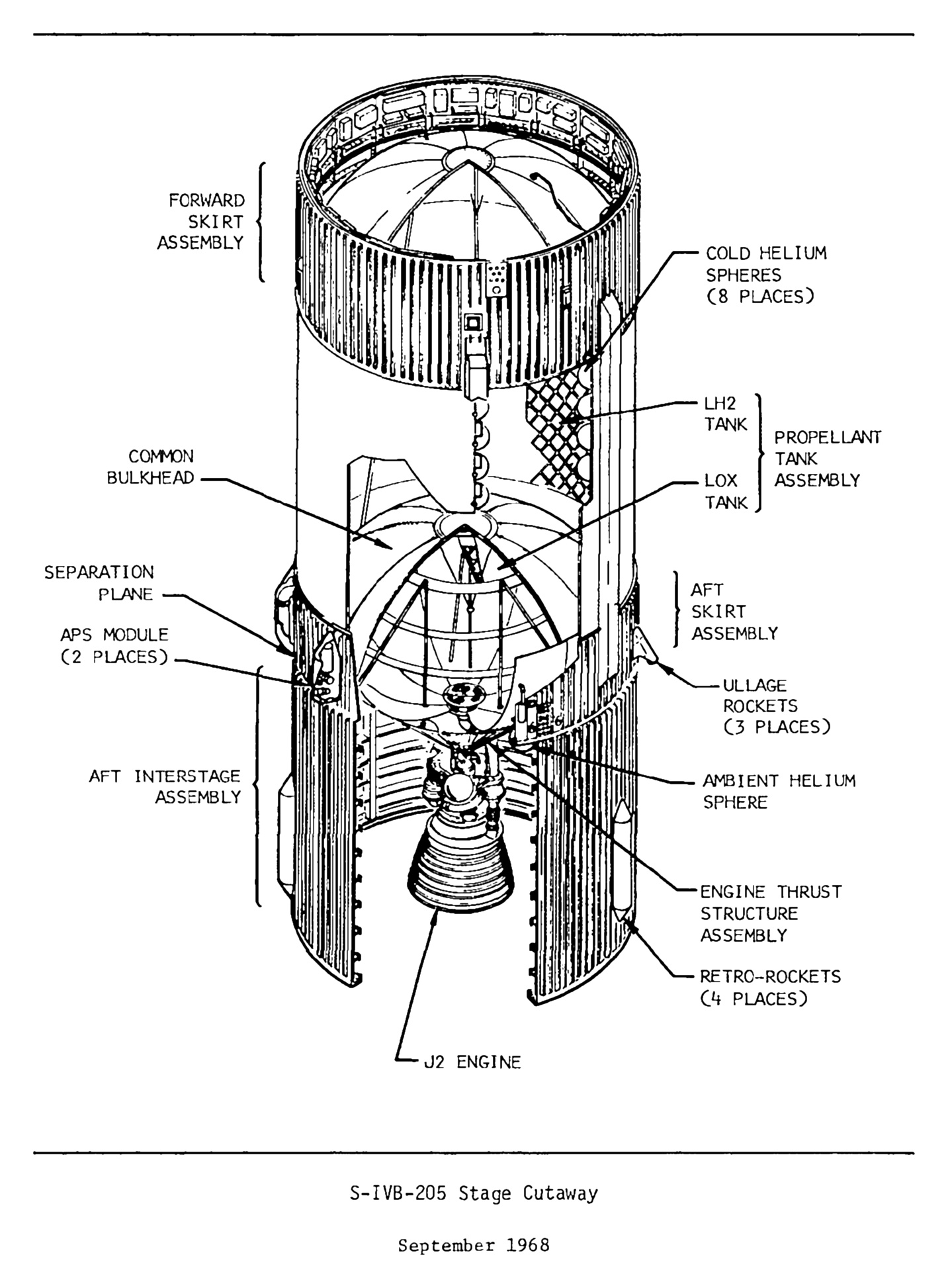
Click image for a 1433x1946 pixel version of this image in a new window.
Taken from the page 4-4 (p. 66 in the PDF) of S-IVB-205 Stage Flight Test
Plan.
Extraction and cleanup by heroicrelics.
This diagram calls out a number of components and features:
- Forward skirt assembly
- Common bulkhead
- Separation plane
- APS module (2 Places)
- Aft interstage assembly
- J-2 engine
- Cold helium spheres (8 Places)
-
Propellant tank assembly:
- LH2 tank
- LOX tank
- Aft skirt assembly
- Ullage rocket (3 Places)
- Ambient helium sphere
- Engine thrust structure assembly
- Retro-rockets (4 Places)