
S-II Overview
The S-II, the second stage of the Saturn V rocket, was the largest liquid hydrogen stage produced in the 1960s. Equipped with five J-2 rocket engines, it produced about 1,000,000 pounds of thrust. It was 33 feet in diameter and 81 ft. 7 in. high.
Click image for a 5502x4483 pixel version of this image in a new window.
From the cover of the Propulsion and Fluid Systems Components Manual for
the S-II Stage of the Saturn V, located in the Dunaway collection of the
Dept. of Archives/Special
Collections, M. Louis Salmon Library, University of Alabama in
Huntsville.
Scan and restoration by heroicrelics.org.
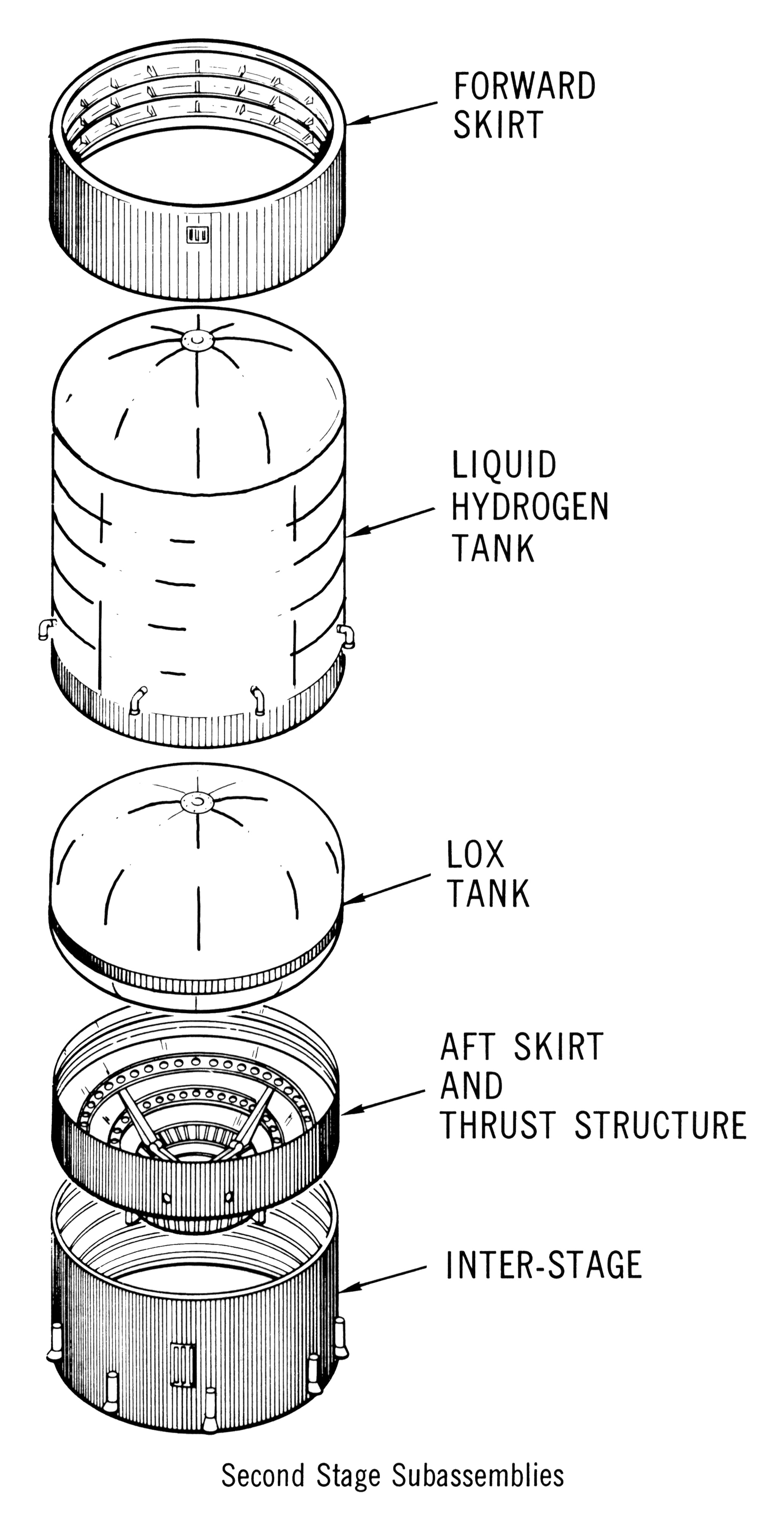
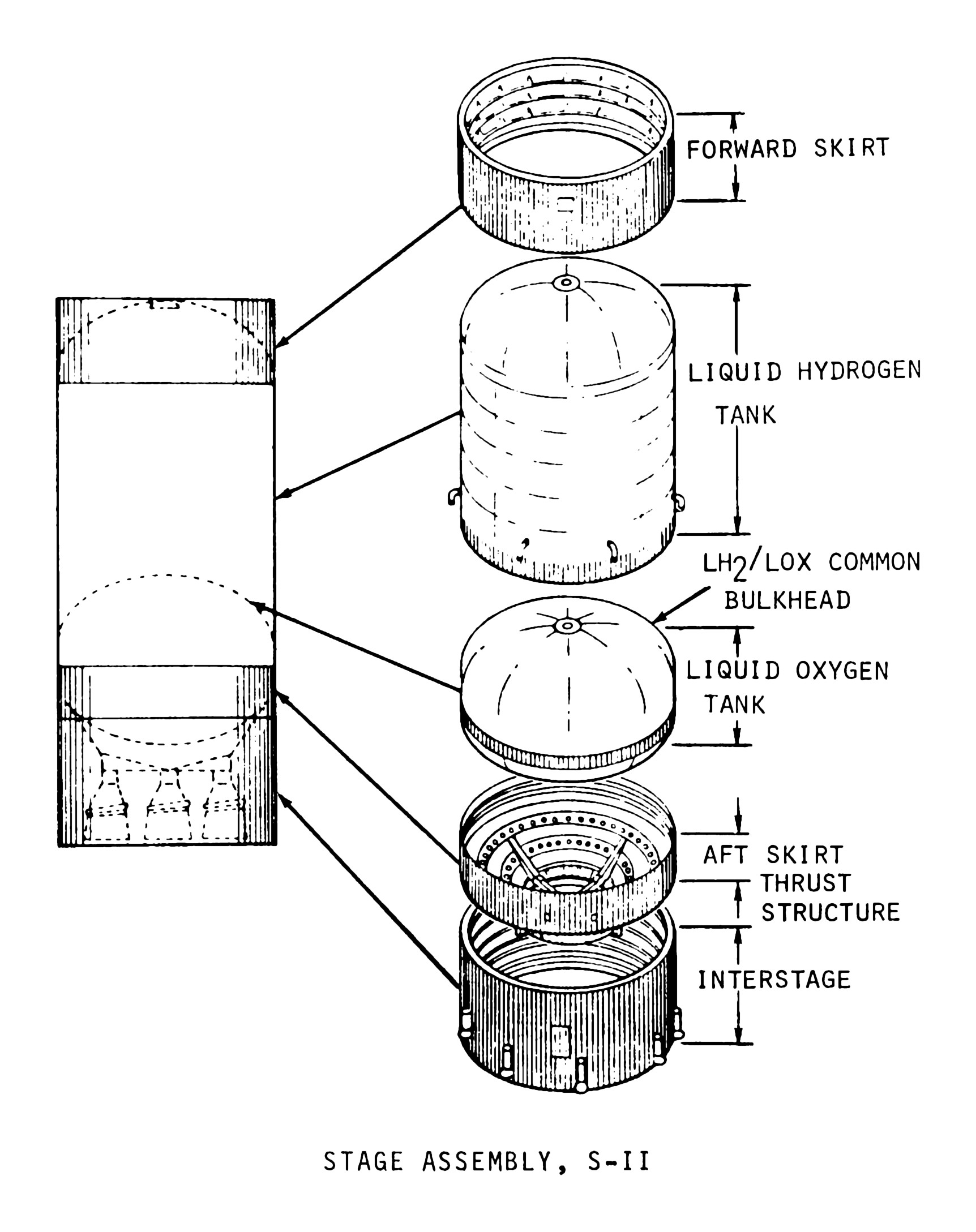
Structurally, the S-II stage consisted of
- An aft interstage, which mated the stage to the S-IC first stage. Although I tend to associate the interstages with the lower stage, the interstage was properly part of the S-II.
- A cylindrical aft skirt, to which was connected the thrust structure, a truncated cone (or frustum). The engines were mounted to the thrust structure, which transmitted the thrust to the aft skirt, which in turn transmitted the thrust to the propellant tank walls.
- A liquid oxygen tank and a liquid hydrogen tank. Rather than each tank having customary hemispherical bulkheads at both ends (and separated by an intertank structure, as with the S-IC), the forward end of the LOX tank and the aft end of the LH2 tank were separated by a common bulkhead. The common bulkhead consisted of honeycomb insulation separating the two aluminum sheets forming the ends of the respective propellant containers; the honeycomb insulation was necessary to prevent the LH2's -423° temperature from freezing the liquid oxygen. The insulation was 5 1/8" thick at the forward end of the common bulkhead and tapered off toward the aft end. The use of the common bulkhead shortened the stage by about 10 feet and saved nearly 4½ tons of weight. The LOX tank held 83,000 gallons and the LH2 tank held 260,000 gallons.
- A cylindrical forward skirt, attached to the forward end of the LH2 tank, which transmitted the thrust loads to the S-IVB stage.
Click image for a 1618x1960 pixel version of this image in a new window.
From page 4-2 of the Saturn V News Reference, located in the Dept. of Archives/Special
Collections, M. Louis Salmon Library, University of Alabama in Huntsville.
Also available on the mirror as a 4.9
megabyte PDF.
Scan by heroicrelics.org.
A similar diagram, locating each component in the overall stage:
Click image for a 1724x2177 pixel version of this image in a new window.
Adapted from page A-29 (p. 265 in the PDF) of Apollo/Saturn V
Space Vehicle Selected Structural Element Review Report, AS-503 (alternate
link).
Extraction and adaptation by heroicrelics.org.
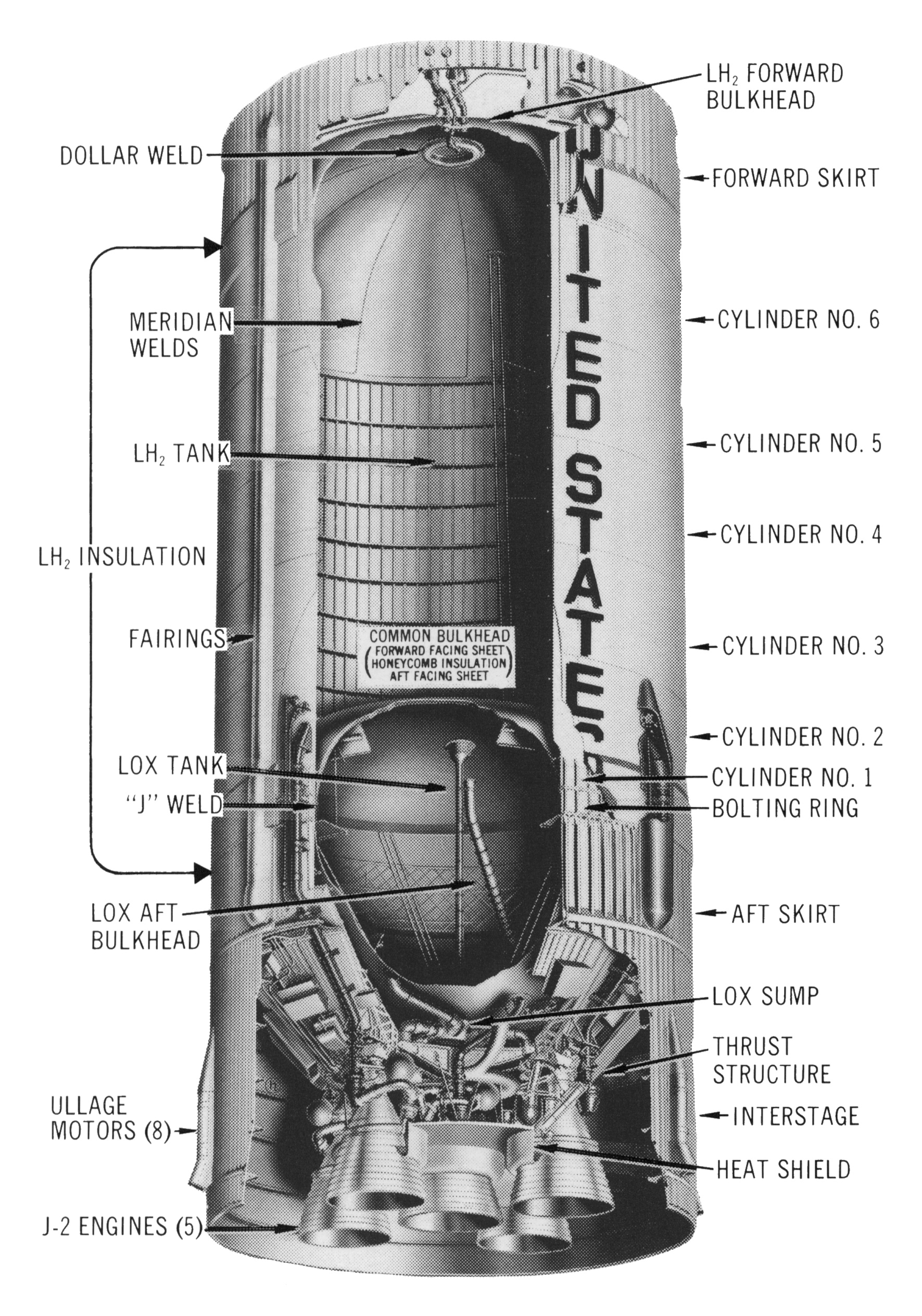
This cut-away diagram shows the major structural elements assembled into the final stage, while at the same time showing the interior of stage subassemblies.
Click image for a 1771x2528 pixel version of this image in a new window.
From an unnumbered page at the beginning of Section 4 of the Saturn V
News Reference, located in the Dept. of Archives/Special
Collections, M. Louis Salmon Library, University of Alabama in Huntsville.
Also available on the mirror as a 4.9
megabyte PDF.
Scan by heroicrelics.org.
Callouts in this diagram include
- Dollar Weld
- Meridian Welds
- LH2 Tank
- LH2 Insulation
- Fairings
- LOX Tank
- "J" Weld
- LOX Aft Bulkhead
- Ullage Motors (8)
- J-2 Engines (5)
- LH2 Forward Bulkhead
- Forward Skirt
- Cylinder No. 6
- Cylinder No. 5
- Cylinder No. 4
- Cylinder No. 3
- Cylinder No. 2
- Cylinder No. 1
- Bolting Ring
- Aft Skirt
- LOX Sump
- Thrust Structure
- Interstage
- Heat Shield
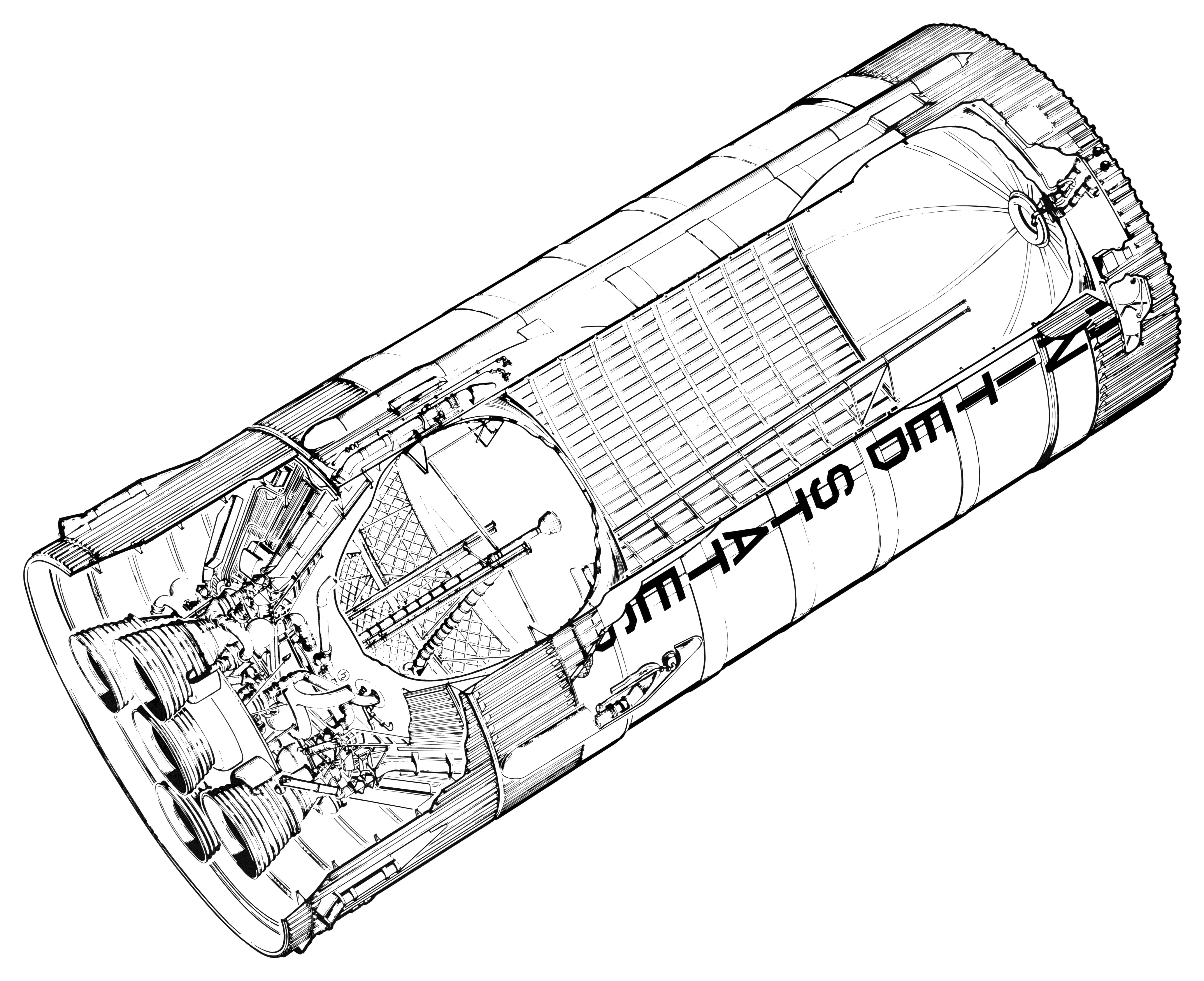
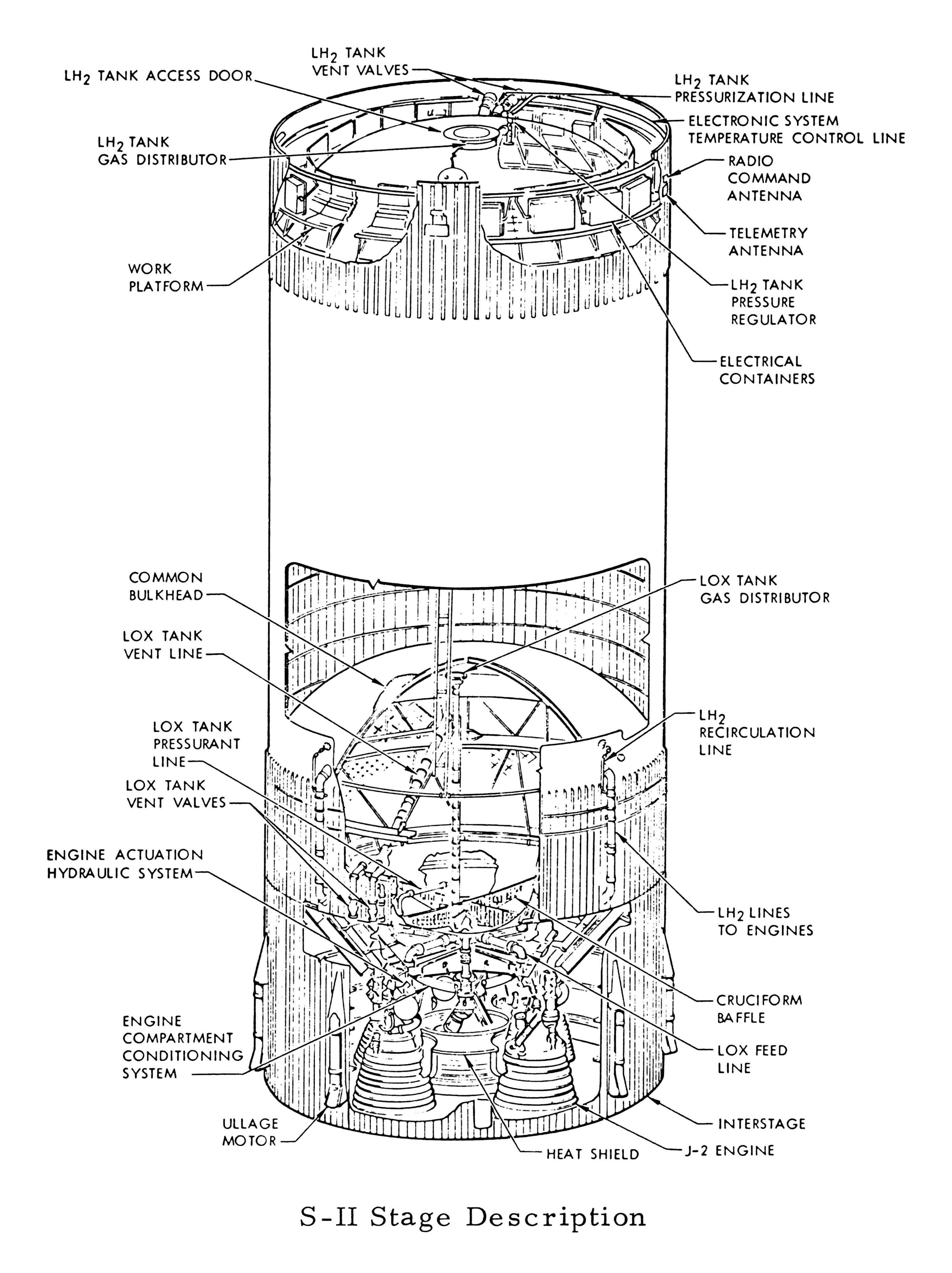
Another detailed, cutaway diagram:
Click image for a 3038x4060 pixel version of this image in a new window.
From page 4 of my Engineering Course
for Saturn S-II Stage Systems for NASA, Volume 1: Introduction (SD
68-654-1).
Scan and cleanup by heroicrelics.org.
Callouts in this diagram include
- LH2 Tank Vent Valves
- LH2 Tank Access Door
- LH2 Tank Gas Distributor
- Work Platform
- Common Bulkhead
- LOX Tank Vent Line
- LOX Tank Pressurant Line
- LOX Tank Vent Valves
- Engine Actuation Hydraulic System
- Engine Compartment Conditioning System
- Ullage Motor
- LH2 Tank Pressurization Line
- Electronic System Temperature Control Line
- Radio Command Antenna
- Telemetry Antenna
- LH2 Tank Pressure Regulator
- Electrical Containers
- LOX Tank Gas Distributor
- LH2 Recirculation Line
- LH2 Lines to Engines
- Cruciform Baffle
- LOX Feed Line
- Interstage
- J-2 Engine
- Heat Shield
The diagrams above show 8 ullage motors, used to settle the S-II propellants after staging. Only SA-501 (Apollo 4) flew with 8 ullage motors; it was found that four ullage motors could provide adequate propellant seating and stage separation, so SA-502 (Apollo 6) deleted four of the ullage motors (but retained the empty fairings) and SA-503 (Apollo 8) through SA-509 (Apollo 14) had only four ullage motors and fairings. It was later decided that the ullage motors were entirely unnecessary, so SA-510 (Apollo 15) and subsequent deleted the ullage motors and fairings entirely.
Of course, each of the S-II's structural elements themselves were gargantuan structures, comprised of subassemblies. This diagram breaks down several structures into their components, including the LH2 forward bulkhead, six LH2 cylinder subassemblies, the common bulkhead, the aft bulkhead, and the interstage. This diagram additionally calls out two pieces of ground support equipment, the forward hoisting frame and the static firing skirt:
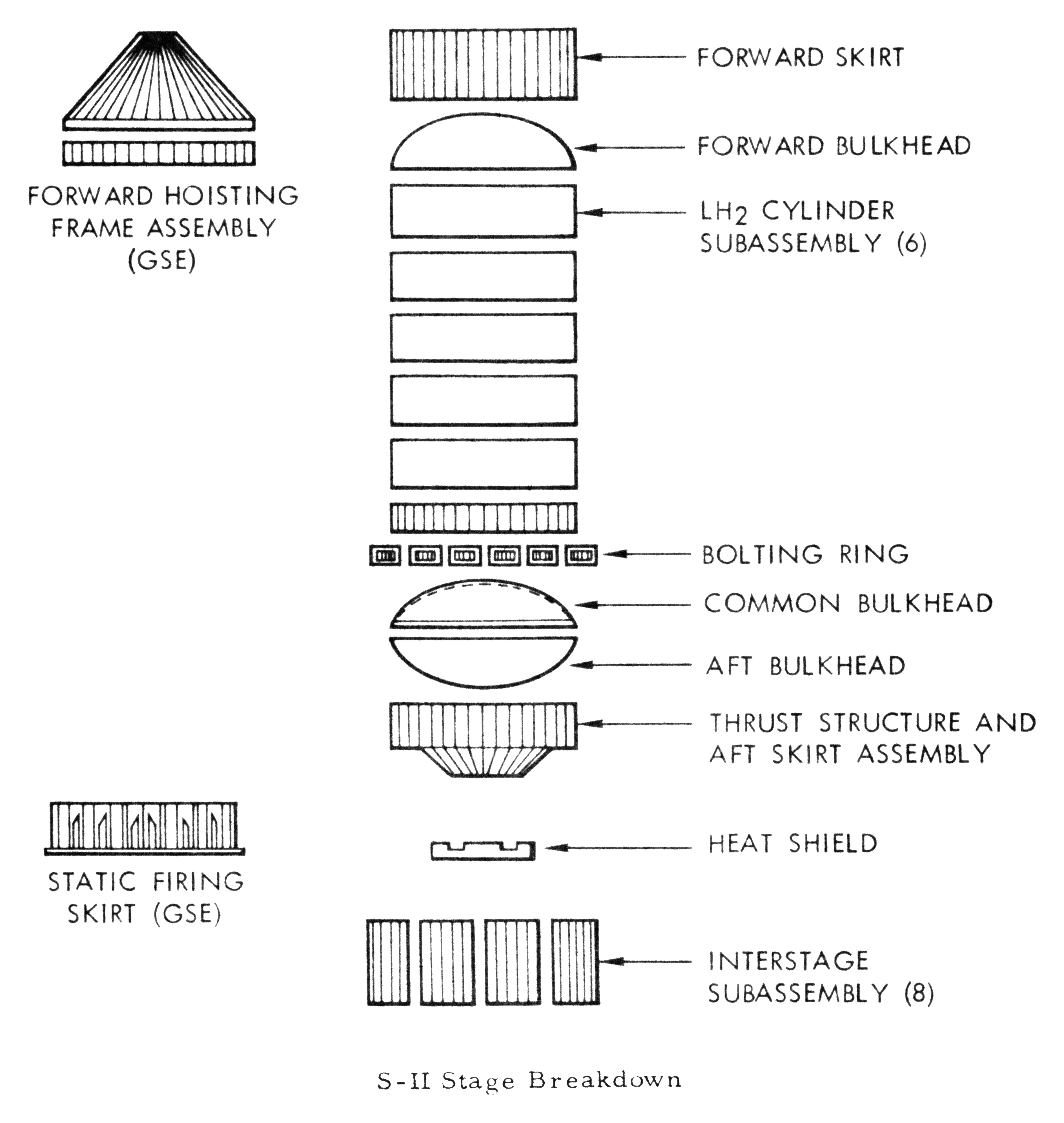
Click image for a 3776x3986 pixel version of this image in a new window.
Taken from page 1-2 of the Manufacturing Plan for Saturn S-II, Stages
16-15, located in the Dept. of Archives/Special
Collections, M. Louis Salmon Library, University of Alabama in Huntsville,
which makes the document available as a 8.1
megabyte PDF.
Extraction and cleanup by heroicrelics.org.
This final diagram breaks each subassembly down into its component parts:
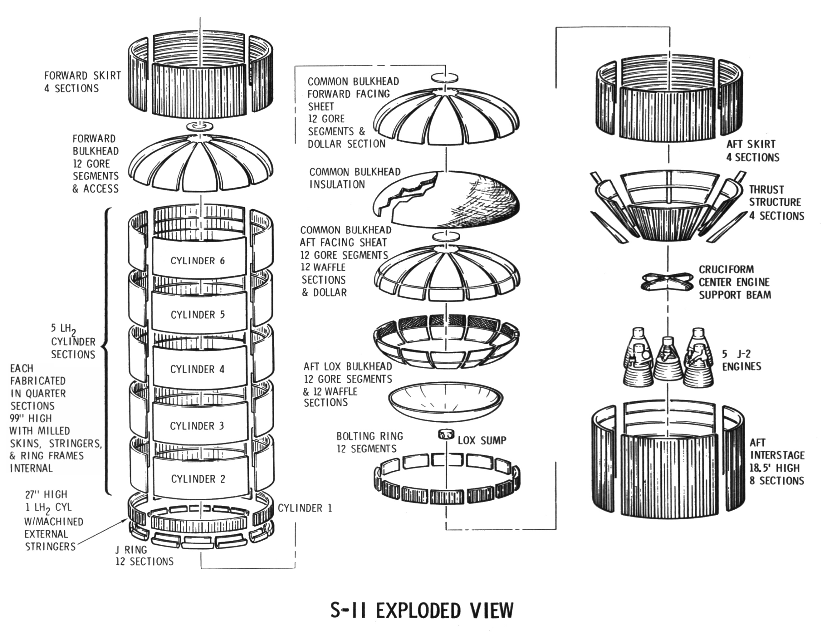
Click image for a 2634x2028 pixel version of this image in a new window.
Taken from page 9 in the PDF of the Description of S-II
Stage Structures
Extraction and cleanup by heroicrelics.org.
The liquid hydrogen tank was the largest subassembly and was also composed of the largest number of parts. The Description of S-II Stage Structures describes LH2 tank as follows:
The LH2 tank is made up of six cylindrical sections, an ellipsoidal forward bulk[sic] and the common bulkhead. The volume of the LH2 tank is 36,883 cu. ft. The forward bulkhead and the cylindrical sections are of 2014 aluminum covered with external insulation.
The cylindrical sections are made up of quarter panels welded together. The quarter panels have integral longitudinal and circumferential stiffeners. Riveted to the circumferential stiffeners are 7 inch wide rings of 2024 aluminum for additional support. The aft cylindrical section has external tapered longitudinal stiffeners 25 inches long to assist in transferring loads from the bolting ring to which it is fastened. The bolting ring is 15 inches long and has provision for attachment of the LOX tank, the aft skirt and the LH2 cylinder.
The forward cylindrical section has a boss at the forward end to which is bolted the forward skirt. The forward bulkhead is welded to this section.
The forward bulkhead is constructed of 12 welded gores and a circular section welded at the center. Access to the tank is through a manhole in the center of the forward bulkhead.
One fitting for pressurization and two for venting are provided in the forward bulkhead. Five fittings for LH2 engine lines, one for LH2 recirculation return line, and one for fill and drain are provided in the cylindrical section just forward of the bolting ring.
Installed in the interior of the tank is the continuous level probe and a pressurization gas diffuser.
Insulation on the cylindrical section and the forward bulkhead is external to the tank. It consists of glass-phenolic honeycomb core filled with isocyanate foam covered with a nylon phenolic skin and sealed with a plastic film. Provision is made in the insulation for purging and a leak detection system. Insulation on the bolting ring is machined blocks of plastic.
Note that the external insulation as described above was used on the various testing S-II stages and the first seven flight stages (the unmanned Apollos 4 and 6, plus Apollos 8 through 12). Starting with S-II-8 (used on SA-508, or Apollo 13), an external spray-on foam, not unlike the foam used on the Space Shuttle External Tank, was used instead.