S-II Stage Pressurization System
The two basic functions of the S-II stage inflight propellant tank pressurization system were to meet engine pressure requirements and to help maintain stage structural integrity. Engine pressure requirements were met by ensuring a proper net positive suction head (NPSH) at the engine propellant pump inlets. Without this pressurization, the engine pumps would have been unable to function (lack of a sufficient volume of propellant at the pump inlet would have resulted in cavitation). Maintenance of stage structural integrity was twofold: the stage structure had to be protected from both overpressurization, to avoid rupture, and underpressurization, to avoid buckling during S-IC boost.
The propellant tank pressurization system was composed of two subsystems, the propellant tank pressurization subsystem and the propellant tank venting subsystems. The former supplied the positive propellant tank pressure to ensure that engine NPSH requirements were met and that structural requirements were satisfied during S-IC boost. The latter guarded against overpressurization, assuring proper engine operation and structural integrity. The potential sources of overpressurization were propellant boiloff and pressurization system malfunction.
Propellant Tank Pressurization Subsystem
The propellant tank pressurization subsystem comprised two sections: LOX tank pressurization and LH2 tank pressurization.
Click image for a 5383x4169 pixel version of this image in a new window.
Adapted from page 101 of my Engineering
Course for Saturn S-II Stage Systems for NASA, Volume 2: S-II Stage Propulsion
and Mechanical Systems.
Scan, cleanup, and adaptation by heroicrelics.org.
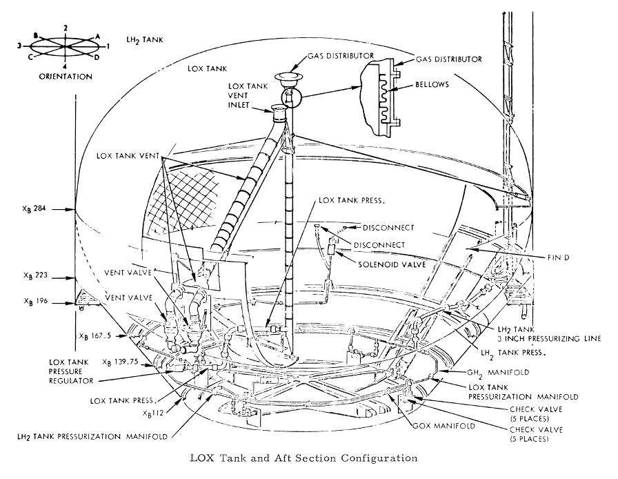
GOX was formed by evaporating LOX in one coil of the J-2 engine's four-coil heat exchanger. Heat for evaporation came from the exhaust gases of the LOX pump turbine. Gaseous oxygen from all five engines was collected in a manifold and conducted through a regulator and gas distributor into the LOX tank ullage space. The regulator sensed the pressure in the vent line, which was directly connected to the ullage space, and opened or closed to control the rate of flow of pressurant.
GH2 was bled from the engine injector and was collected from the four outboard engines in a manifold; it was then conducted up the side of the stage (through the systems tunnel), through a regulator and gas distributor, and into the ullage space. The regulator sensed the pressure in the vent line, which was connected directly to the ullage space, and maintained the ullage pressure by regulating the rate of pressurant flow.
During the first 300 seconds (for AS-503 and subsequent vehicles; 320 seconds for AS-501 and AS-502) of S-II flight, the GH2 regulator acted to control the rate of pressurant flow to the LH2 tank. At the end of this period, the regulator opened to its full-open position (step pressurization), and the pressure in the tank was allowed to rise to the vent-valve cracking pressure.
Because propellant tank pressurization during flight required the engines to be operative, no active tank pressurization occurred from liftoff and until S-II ignition. To maintain the structural integrity of the stage and to ensure that the engines started properly, the tanks were prepressurized at a high enough level to allow a reasonable amount of pressure decay between liftoff and the time when the onboard pressurization system was active.
Venting Subsystem Features
The vent valves prevented overpressurization by permitting the outflow of excessive gas from the propellant tanks. In flight, the vent valves were opened by excessive tank pressures that acted through a pilot mechanism. Gas from all valves was vented directly overboard .
The LH2 tank venting was controlled by two 7 inch diameter valves. These valves were located at the end of two vacuum-jacketed lines that led from the tank ullage space and discharged through the vent disconnects.
The LOX tank was vented by conducting excess gas in a vent line that branched into two 7-inch lines. Two vent valves controlled the discharge of excess gas by sensing the vent line pressure and opening when the pressure reached a predetermined level.
The bulk of the descriptive text on this page was taken, largely verbatim, from the Engineering Course for Saturn S-II Stage Systems for NASA, Volume 2: S-II Stage Propulsion and Mechanical Systems.

