General S-IC Stage (Saturn V First Stage) Diagrams
I come across many S-IC diagrams which, while interesting, are not so interesting that they necessarily merit their own separate page. I have created this page as a repository for such diagrams.
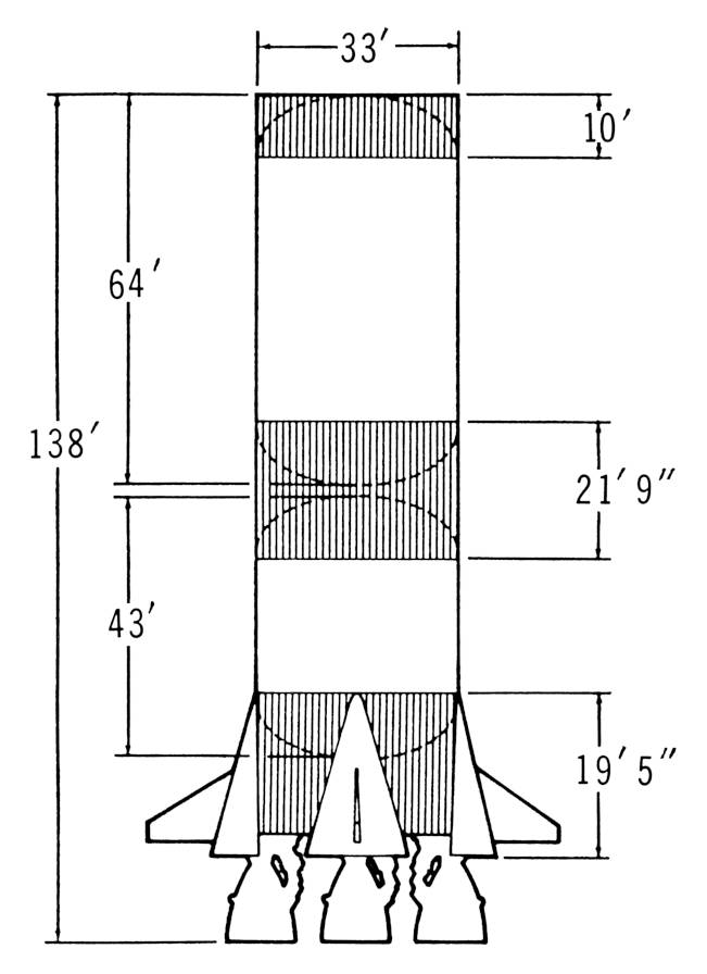
The Saturn V News Reference's S-IC chapter includes a diagram of the S-IC stage.
Click image for a 1747x2406 pixel version of this image in a new window.
From the first unnumbered page of the Saturn V News Reference (August
1967)'s "First Stage" section. Located in the Saturn V
Collection, Dept. of
Archives/Special Collections, M. Louis Salmon Library, University of
Alabama in Huntsville, which also makes a slightly different revision of this
document available
electronically.
Scan and cleanup by heroicrelics.
The diagram contains various dimensional information about the stage:
- Stage width: 33'
- Overall stage height: 138'
- Liquid oxygen tank height: 64'
- RP-1 tank height: 43'
- Forward skirt height: 10'
- Intertank height: 21' 9"
- Thrust structure height: 19' 5"
The following S-IC-related information is also included in the section's "First Stage Fact Sheet":
-
Weight: 303,000 lb. (dry) 4,881,000 lb. (loaded) - Diameter: 33 ft.
- Height: 138 ft.
- Burn Time: About 2.5 min.
- Velocity: 6,000 miles per hour at burnout (approx.)
- Altitude at Burnout: About 38 miles
-
Major Structural Components
- Thrust Structure
- Fuel Tank
- Intertank
- LOX Tank
- Forward Skirt
-
Major Systems
-
Propulsion: Five bipropellant F-1 engines
- Total thrust: 7.5 million lb.
-
Propellant: RP-1—209,000 gal. or 1,400,000 lb. LOX—334,500 gal. or 3,178,000 lb. -
Pressure: Control—1.27 cubic feet of gaseous nitrogen at 3,250 psig Fuel pressurization—124 cubit feet or 636 lb. of gaseous helium at 3,100 psig LOX pressurization—gaseous oxygen converted from 6,340 pounds of LOX by the engines
- Hydraulic: Power primarily for engine start and for gimbaling four outboard engines.
- Electrical: Two 28 VDC batteries, basic power for all electrical functions
- Instrumentation: Handles approx. 900 measurements
- Tracking: ODOP Transponder
-
Propulsion: Five bipropellant F-1 engines
There is a note which states that figures given for weights and contents are average and may vary to meet requirements for the differing missions.
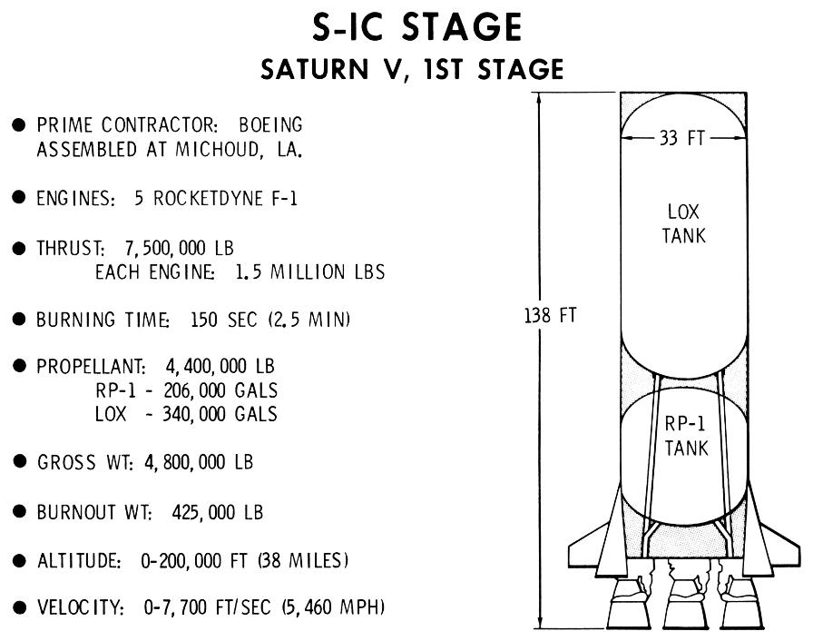
The F-1 Familiarization Training Manual has a diagram of the S-IC stage; this is only natural, as the S-IC stage is the only stage in which the engine was ever mounted.
Click image for a 3446x2717 pixel version of this image in a new window.
From the second unnumbered page of the F-1 Engine Familiarization
Training Manual, located in the archives of the U.S.
Space & Rocket Center. Also available from University
of Alabama at Huntsville's USSRC Archive [direct link to 16.8M PDF
file].
Scan and cleanup by heroicrelics.
The diagram notes the overall stage dimensions as 138 feet long and 33 feet in diameter and shows the LOX tank mounted forward of the RP-1 tank, with the LOX suction lines running through the fuel tank.
The following S-IC-related information is also noted:
-
Prime Contractor: Boeing
Assembled at Michoud, LA. - Engines: 5 Rocketdyne F-1
-
Thrust: 7,500,000 lb
Each engine: 1.5 million lbs - Burning Time: 150 sec (2.5 min)
-
Propellant: 4,400,000 lb
RP-1 - 206,000 gals
LOX - 340,000 gals - Gross Wt: 4,800,000 lb
- Burnout Wt: 425,000 lb
- Altitude: 0-200,000 ft (38 miles)
- Velocity: 0-7,700 ft/sec (5,460 mph)
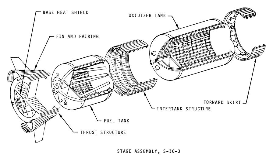
Structurally, the S-IC stage consisted of
-
A 19.5 foot tall thrust
structure, to which the engines were mounted. The thrust of the engines
was transmitted to the propellant tank walls via the thrust structure.
There are four holddown posts located on the periphery of the thrust structure. The entire vehicle was supported by these posts. Hold-down arms on the mobile launcher also clamped the Saturn V to the pad via these holddown posts as the S-IC's five F-1 engines built up thrust after ignition; the hold-down arms released the Saturn V once all of the engines were up to full thrust. -
Four fairings attached to the thrust structure and partially surrounded the
S-IC's outboard engines. The fairings were shaped like cone halves and
smoothed the air flow over the engines. A fin was attached to each
fairing. The fins added to the vehicle's flight stability.
Each fairing also housed two retrorockets. At stage separation, the retros fired, blowing the tips off of the fairings. The retros slowed the S-IC and prevented it from recontacting the S-II. - A fuel, or RP-1, tank. The tank consisted of forward and aft ellipsoidal bulkheads and cylindrical tank walls and was approximately 43 feet tall. Five LOX tunnels ran through the fuel tank, carrying liquid oxygen from the LOX tank, through the fuel tank, and to the engines. Both the fuel and LOX tanks were constructed using a "Y-ring" at both the forward and aft ends of the cylindrical tank wall. The Y-rings connected the tank tank wall to both the tank bulkheads and the adjoining stage structures.
- An intertank structure, approximately 22 feet long. The upper bulkhead of the fuel tank extended up into the intertank and the lower bulkhead of the LOX tank dipped down into it. The forward and aft edges of the intertank each incorporated 216 fittings which mated the intertank to each propellant tank's Y-ring.
- An oxidizer, or LOX, tank. The LOX tank's construction was similar to that of the RP-1 tank and was 64 feet in height. LOX tunnels were connected to the tank's aft bulkhead and ran through the intertank and fuel tank to provide oxidizer to the engines.
- A forward skirt, which was approximately 10 feet long and extended past the LOX tank's forward bulkhead. It provided the connecting link for the S-IC and S-II stages. Various equipment, including telemetry, range safety, and ODOP radar tracking equipment, was mounted on the forward skirt.
Click image for a 2808x1662 pixel version of this image in a new window.
Adapted from page A-10 (p. 246 in the PDF) of Apollo/Saturn V
Space Vehicle Selected Structural Element Review Report, AS-503.
Extraction, cleanup, and adaptation by heroicrelics.org.


