
Saturn I/IB Turbine Exhaust
When designing the S-I stage, the Marshall engineers were concerned about the "base heating" of the vehicle, caused both by the initial heat of the exhaust plumes as well as heating caused by the recirculation of hot gases. The Saturn's designers initially considered a circular arrangement for the engines, but analysis showed that base heating would be excessive. This led to the familiar four inboard/four outboard design; the exhaust from the four inboard engines at the center of the stage would help prevent recirculation of hot gases in that area, and a relatively small flame shield between the engines could be employed to help protect against whatever gases might cause problems.
The Saturn's H-1 engine employed a gas generator (basically a small, inefficient rocket engine) to drive the turbine which powered the fuel and LOX turbopumps: The liquid propellant gas generator created large amounts of hot gas, which flowed through the fan-like turbine, spinning it. The turbine was connected to a shaft leading into a gearbox, which then powered the turbopumps. While the four inboard/four outboard engine arrangement helped minimize base heating from the engine exhaust, the hot gases of the turbine exhaust needed to be removed from the engine area. How the H-1 dealt with this exhaust varied over the Saturn I/IB programs.
The turbine exhaust is fuel-rich. During the Jupiter program, afterburning of such gases caused high heating rates when discharged into the base region, so the turbine exhaust was dumped overboard through a port on the side of the aft skirt. Success in this method of disposal of the turbine exhaust led the designers toward a similar method for the Saturn.
However, there was a problem: On the S-3D (the engine used by the Jupiter missile), the gas generator and turbine are fixed and only the engine's thrust chamber gimballed. On the H-1, the gas generator and turbine were mounted on the engine itself. This simplified construction by allowing the flexible propellant lines required for a gimballing engine to be rated for a lower pressure (since the turbopumps were on the engine itself, the high-pressure section of the propellant lines were located on the engine, rather than requiring high-pressure, flexible propellant lines as would be the case if the turbopump were not mounted on the engine). On the other hand, such an arrangement seemed to necessitate flexible, high-temperature ducting if the turbine exhaust was to be discharged around the periphery of the tail unit.
The Saturn's designers settled on a compromise: while the inboard engines would dump their turbine exhaust through the side of the stage's tail unit, the outboard engines would dispose of the exhaust by expelling it through a hollow, open-ended "shell" or aspirator (sometimes called an "exhausterator", especially in the early Saturn documentation) around the base of the thrust chamber. The turbine exhaust would be carried away by the pressure from the engine exhaust.
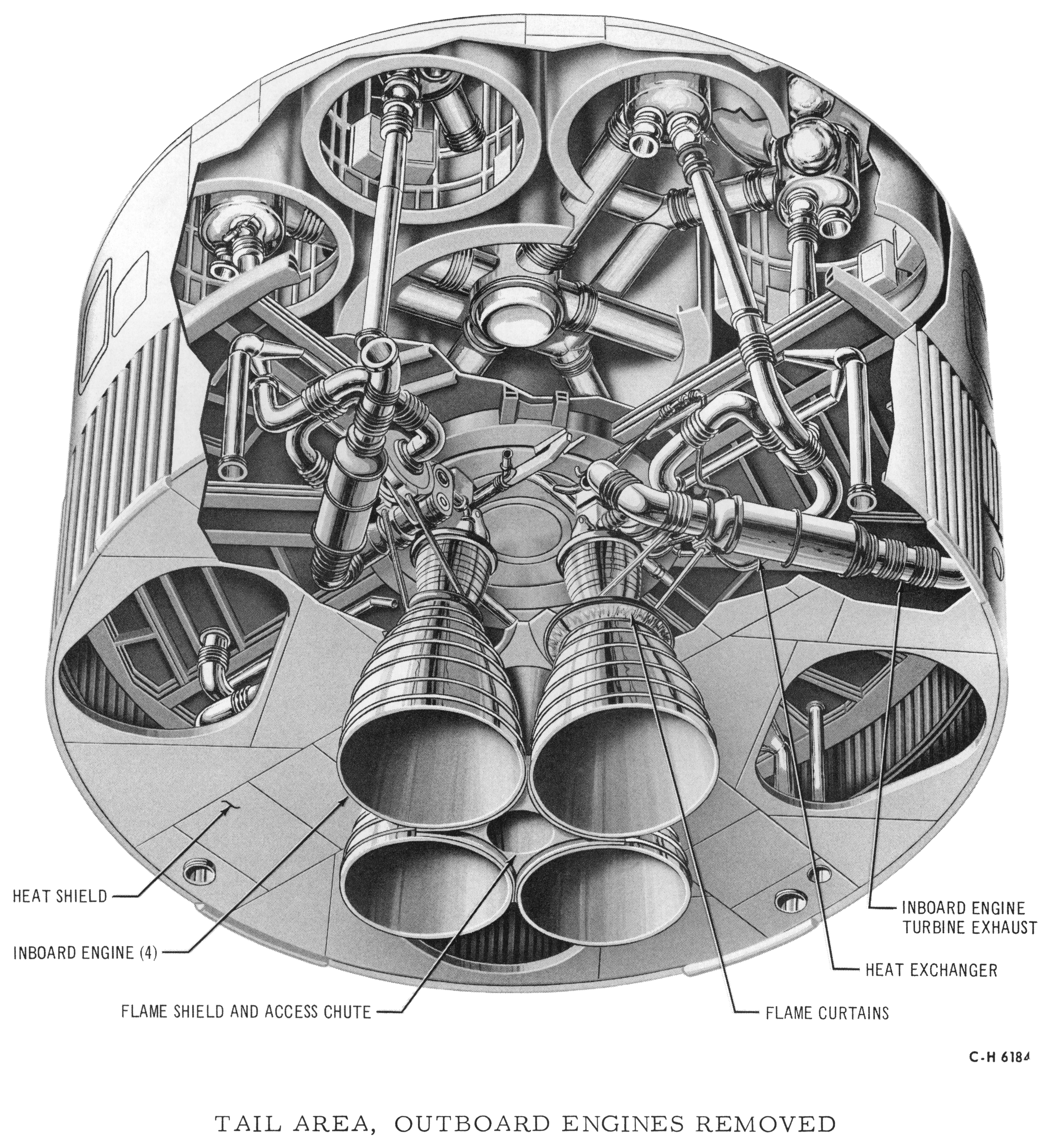
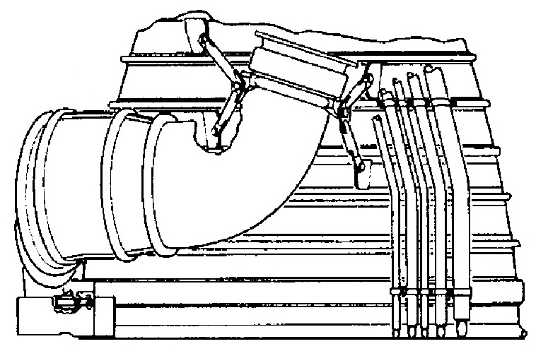
While minor changes were made to the construction of the aspirator, the outboard engines used this same method to vent their turbine exhaust throughout the entire program: Upon leaving the turbine, the exhaust would flow through the heat exchanger (used to covert LOX to GOX to pressurize the LOX containers) and out the aspirator into the engine exhaust stream. Note the liquid propellant gas generator and aspirator in the diagram below.

Click image for a 1000x1290 pixel version of this image in a new window.
Adapted from page II-11 (p. 11 in the PDF) of Saturn
IB Vehicle Handbook, Volume II - S-IB Stage (direct link to 15 MB
PDF) on the USSRC archives hosted by the
University of Alabama - Huntsville.
Extraction, cleanup, and adaptation by heroicrelics.
The exact method by which the turbine exhaust was eliminated from the inboard engines, however, differed in each of the Block I Saturn I, Block II Saturn I, and Saturn IB first stages.
The S-I stages in the Block I Saturn I series routed their inboard engines' turbine exhaust through ducts around the periphery of the tail unit, in vaguely "S"-shaped pipes, as shown in the diagram below and this picture of the SA-T stage at Marshall Space Flight Center.
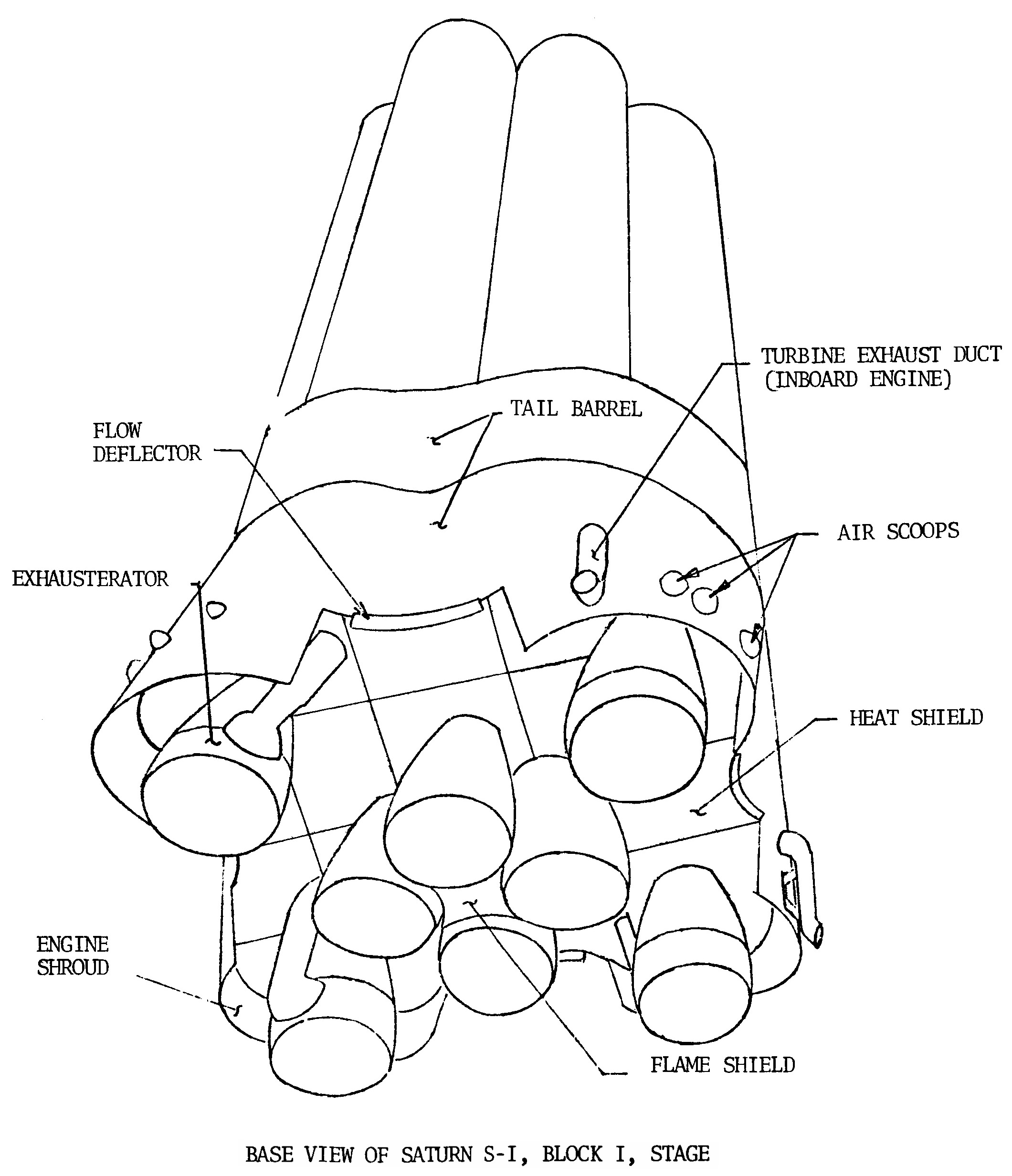
Click image for a 2120x2464 pixel version of this image in a new window.
Taken from page 3-7 (p. 41 in the PDF) of the Saturn
Base Heating Handbook.
Extraction and cleanup by heroicrelics.
The S-I stages of the Block II Saturn I series also routed their inboard engines' turbine exhaust through ducts around the periphery of the tail unit, but the ducts were now shrouded by aerodynamic turbine exhaust fairings (which look like small fins). The turbine exhaust duct can also be seen in the Saturn I Block II Boattail diagram.
Click image for a 4003x4376 pixel version of this image in a new window.
Adapted from page 8 (p. 13 in the PDF) of my SA-5 Saturn I Block II Vehicle
Description.
Scan, cleanup, and adaptation by heroicrelics.
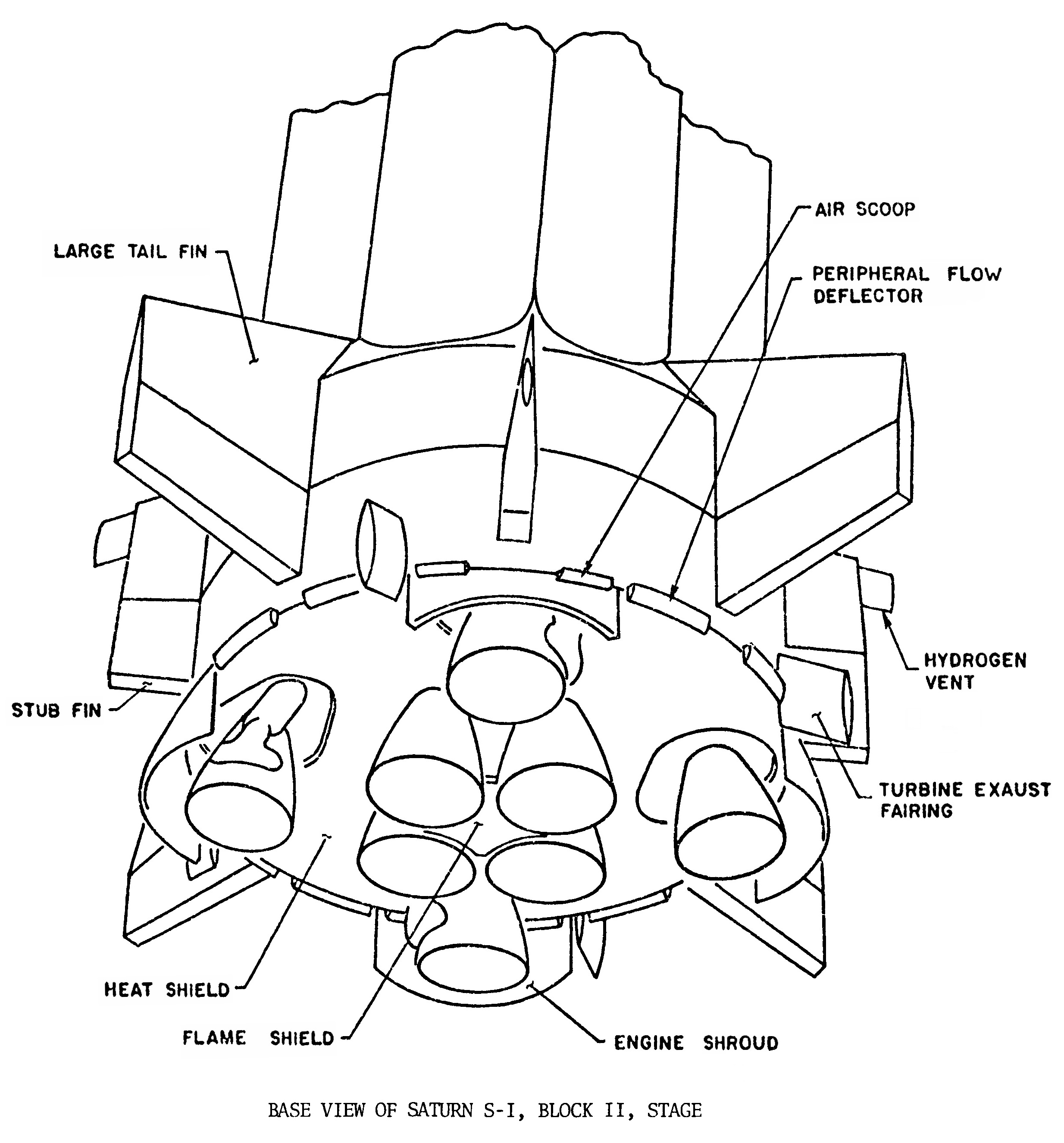
Click image for a 2468x2652 pixel version of this image in a new window.
Taken from page 3-8 (p. 42 in the PDF) of the Saturn
Base Heating Handbook.
Extraction, cleanup, and reconstruction by heroicrelics.
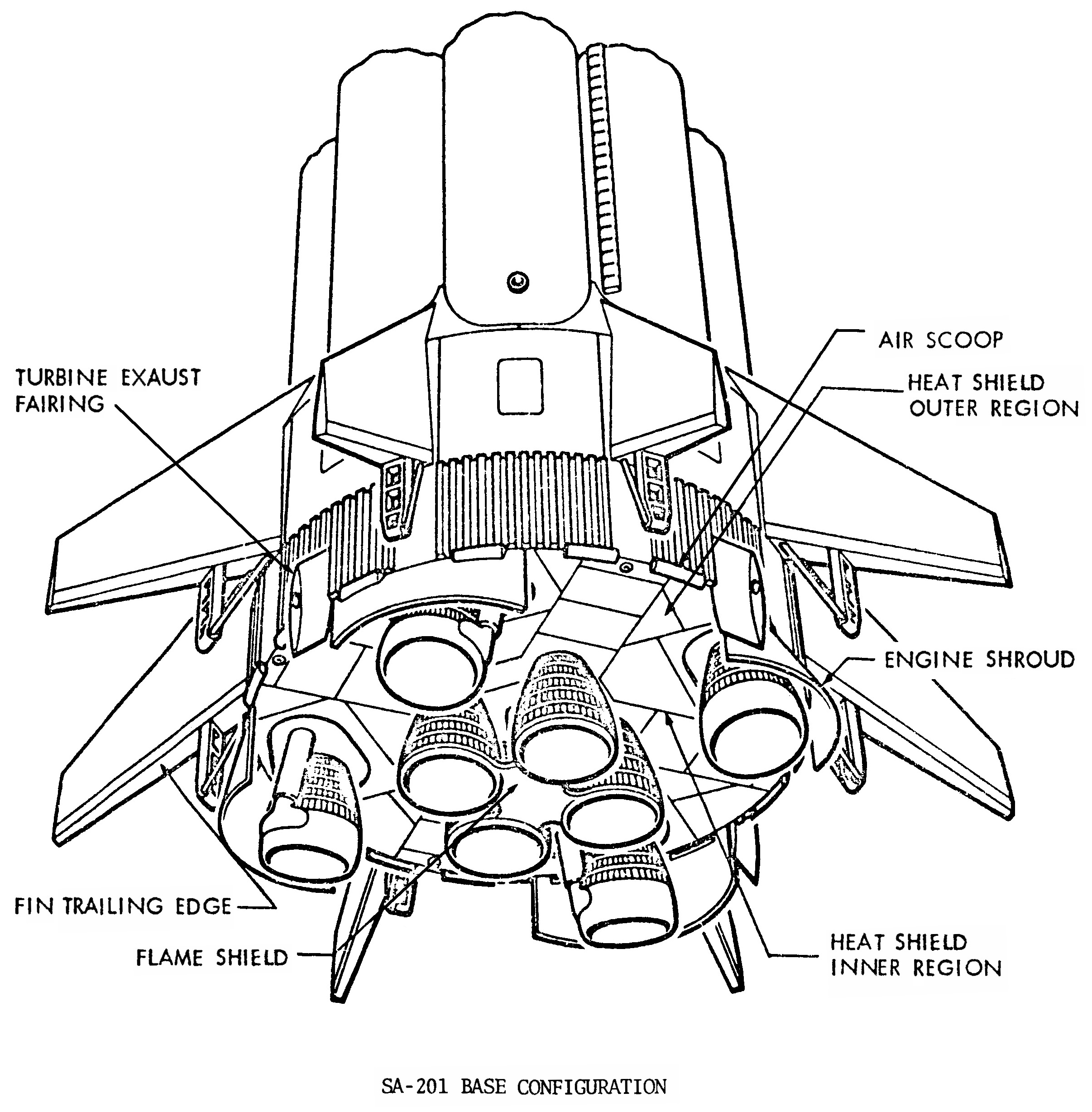
S-IB-1 and S-IB-2, the first two S-IB stages built for the Saturn IB program, used the same basic arrangement as the Block II Saturn I. In fact, when construction on these stages started, they were to be built as Block II S-I stages, but when the Saturn I program was terminated they were completed as S-IB stages. So, although the fins and various other components were redesigned for the Saturn IB program, S-IB-1 and S-IB-2 still used the turbine exhaust fairings on the tail unit (note that S-IB-2 deleted the engine shrouds shown in the diagram below, but was otherwise identical):
Click image for a 2412x2456 pixel version of this image in a new window.
Adapted from page 3-10 (p. 44 in the PDF) of the Saturn
Base Heating Handbook.
Extraction, cleanup, reconstruction, and adaptation by heroicrelics.
The remaining S-IB stages (S-IB-3 and subsequent) rerouted the inboard engines' turbine exhaust. Rather than dumping it through the side of the tail unit, the inboard engines were fitted with "partial aspirators" (or sometimes simply "exhaust ducts"):
Adapted from page 4-8 (p. 65 in the PDF) of the Skylab
Saturn IB Flight Manual.
Extraction and adaptation by heroicrelics.
For photos of an H-1C and its partial aspirator, see my H-1C and H-1D photos page.
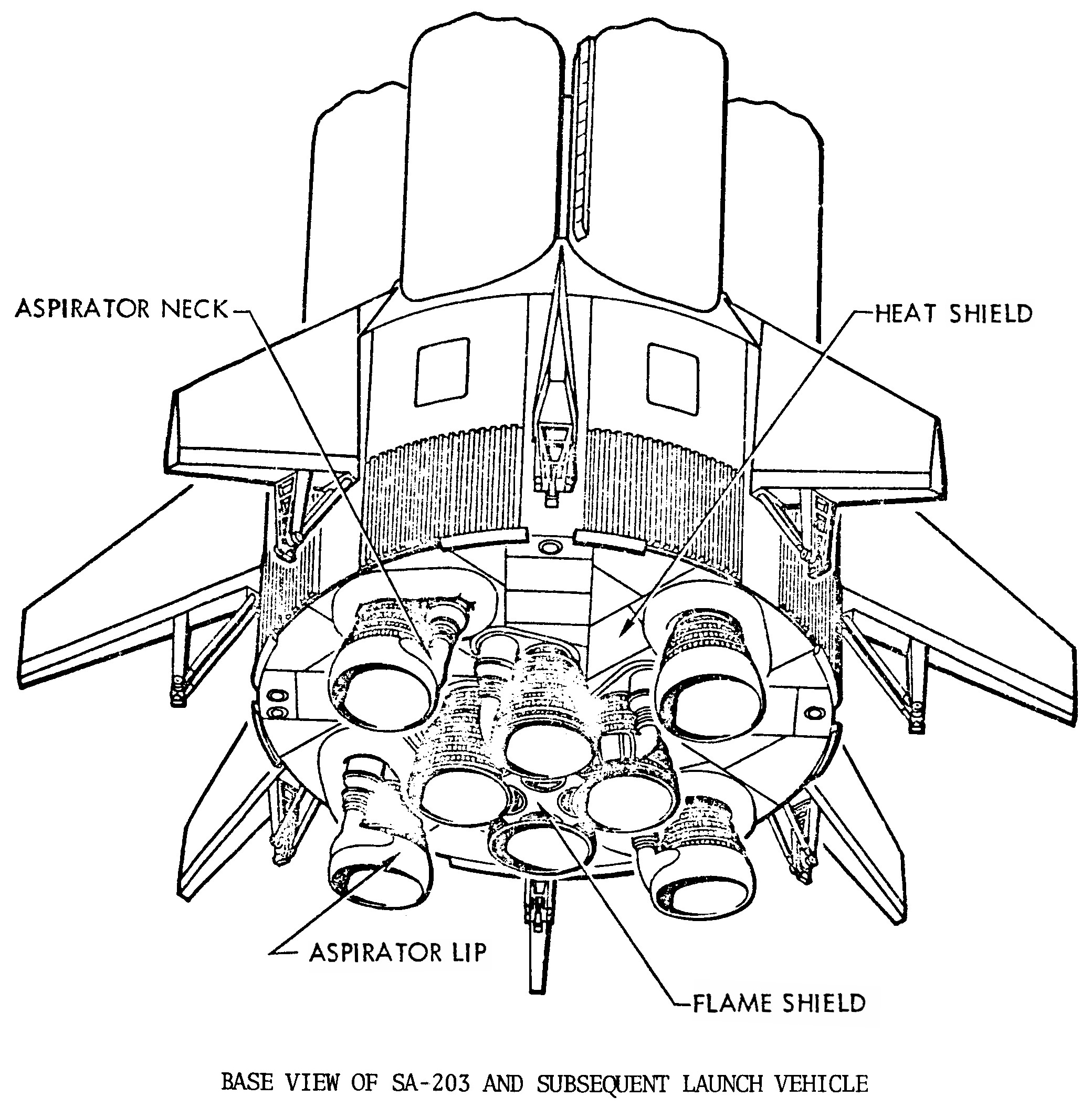
The turbine exhaust was then dumped by the partial aspirators through "D"-shaped cut-outs around the edges of the the flame shield (which now looks like a stylized "X"):
Click image for a 2080x2129 pixel version of this image in a new window.
Taken from page 3-14 (p. 48 in the PDF) of the Saturn
Base Heating Handbook.
Extraction and cleanup by heroicrelics.
So then, the early Saturns (all of the Saturn I S-I stages, plus S-IB-1 and S-IB-2 from the Saturn IB series) had an inboard engine and flame shield arrangement like this, with their turbine exhaust dumped around the circumference of the tail unit:

Click image for a 1418x2116 pixel version of this image in a new window.
Adapted from page 3-16 (p. 50 in the PDF) of the Saturn
Base Heating Handbook.
Extraction and adaptation by heroicrelics.
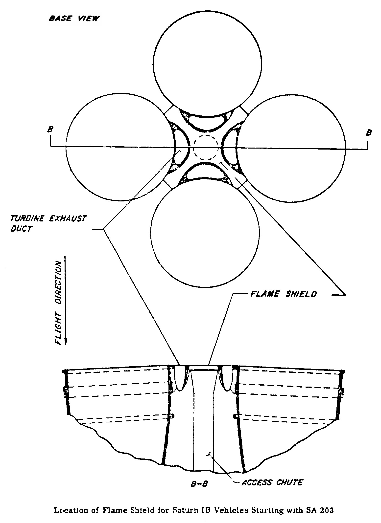
The later Saturn IBs (S-IB-3 and subsequent) had an inboard engine and flame shield arrangement like this, with their turbine exhaust dumped through their partial aspirators and out the flame shield:
Click image for a 1540x2116 pixel version of this image in a new window.
Adapted from page 3-16 (p. 50 in the PDF) of the Saturn
Base Heating Handbook.
Extraction and adaptation by heroicrelics.
I'm not entirely certain as to what led to this engineering change, other than that perhaps flight experience showed that routing the turbine exhaust around the outside of the tail unit was overly conservative. I imagine that the partial aspirators would be lighter than the ducting required to go from the center to the edge of the stage.
Furthermore, I'm uncertain as to why S-IB-1 and S-IB-2 used the old, Block II Saturn I method of eliminating turbine exhaust, other than perhaps that these two stages were built from the canceled S-I-111 and S-I-112 Block II Saturn I stages. Perhaps the stages were sufficiently far along in their construction that it would have been too expensive or too disruptive to the schedule to retrofit the new method of turbine exhaust.