H-1 Heat Exchanger
The heat exchanger is part of the Saturn I/IB LOX pressurization system. Hot turbine exhaust gases flow are routed through the heat exchanger prior to venting into the engine's exhaust stream. Liquid oxygen (LOX) flows through coils inside the heat exchanger and is converted to gaseous oxygen (GOX), where it is returned to the oxidizer containers to provide pressurization.
The combustion gases, produced by the gas generator, drive the turbine and are vented through the turbine exhaust hood into the heat exchanger, where the heat of the gases is used to convert liquid oxygen (LOX) into gaseous oxygen (GOX) for vehicle systems use. The fuel-rich exhaust gases then enter the thrust chamber aspirator or the exhaust duct to be directed into the thrust chamber exit flow stream.
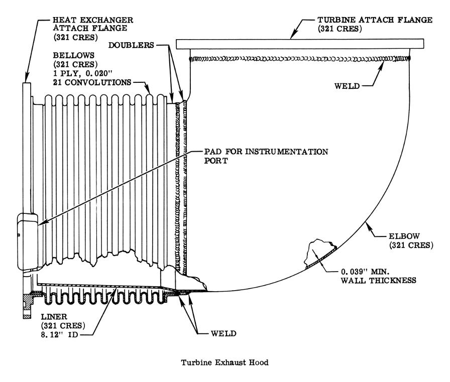
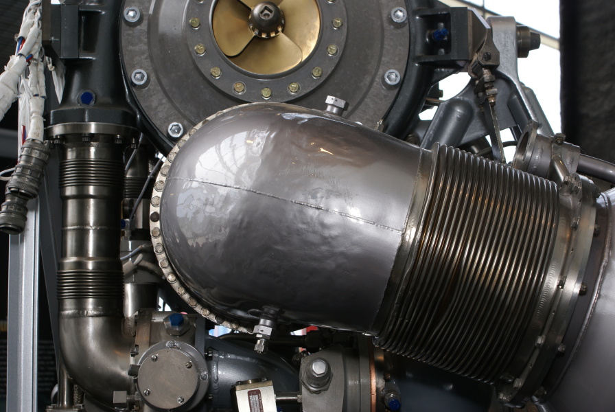
The turbine exhaust hood is a stainless-steel, welded elbow assembly incorporating two mating flanges, two doubler rings, a bellows section, and an integral liner to protect the bellows section. The bellows section permits movement of the system due to heating.
Click image for a 4645x3946 pixel version of this image in a new window.
Adapted from page 87 of H-1 Rocket Engine Technical Data
(R-3620-1A), located in a private collection.
Scan and adaptation by heroicrelics.org.
A turbine exhaust hood installed on an H-1 engine:
Click image for more information about this picture; opens in a new window.
Photo by heroicrelics.org.
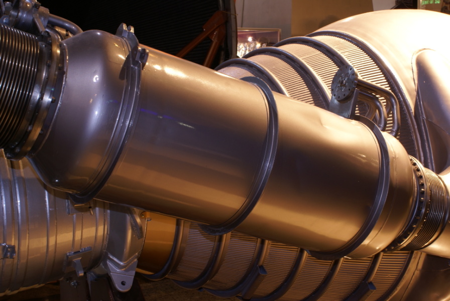
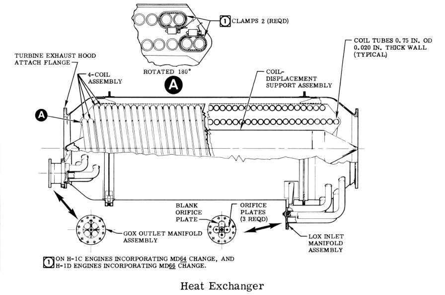
The heat exchanger is a welded, stainless-steel assembly consisting of an outer shell; inlet and outlet flanges; a helix-wound, four-coil system; and coil inlet and outlet manifolds.
Click image for more information about this picture; opens in a new window.
Photo by heroicrelics.org.
Turbine exhaust gases passing through the shell heat the coils. Liquid oxygen (LOX), under turbopump pressure, enters three coils of the four-coil system, to be converted to gaseous oxygen (GOX) for vehicle system use. The fourth coil is blanked off and not utilized. Later versions of the engine had a clamp installed on the two top coils of both the inside and outside coils opposite the GOX outlet to prevent coil movement and possible damage by holding coils firmly against the coil displacement support assembly.
Click image for a 4145x2743 pixel version of this image in a new window.
From the page 1-27 of the H-1 Rocket Engine Models H-1C and H-1D
Technical Manual: Engine Data. Located in the Saturn V Collection, Dept. of Archives/Special
Collections, M. Louis Salmon Library, University of Alabama in Huntsville,
which also makes this document available as a 14.4
megabyte PDF.
Scan, cleanup, and adaptation by heroicrelics.
For photos of the interior of an H-1 heat exchanger, see my photos of the cut-away H-1 rocket engine at the Kansas Cosmosphere or the H-1 engine by the Marshall Space Flight Center Static Test Tower.
The bulk of the text on this page was taken, largely verbatim, from H-1 Rocket Engine Models H-1C and H-1D Technical Manual: Engine Data and the Skylab Saturn IB Flight Manual.


