
S-I LOX Pressurization System
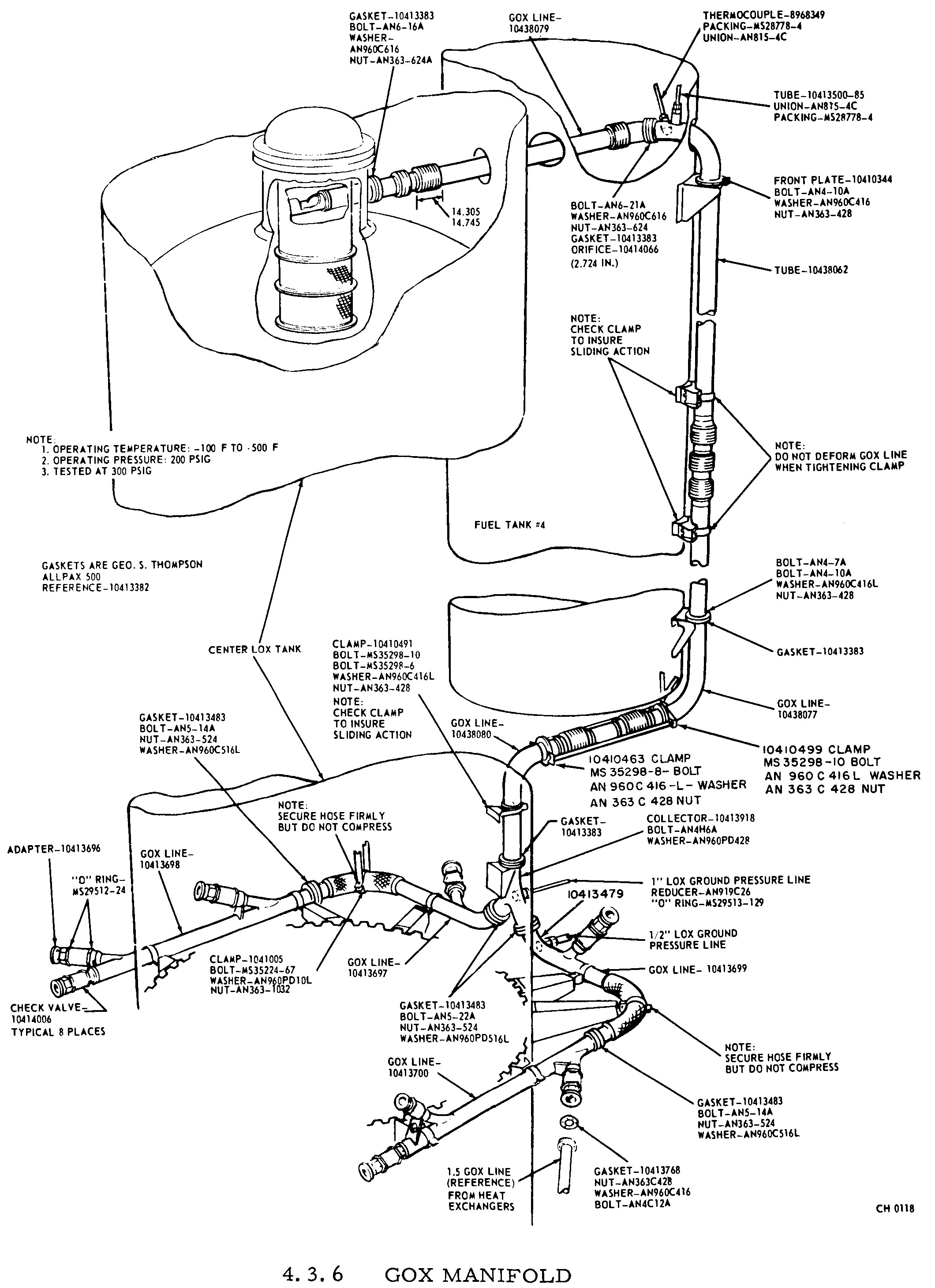
There are five liquid oxygen tanks on the S-I stage: a 105-inch tank at the center of the cluster, surrounded by four 70-inch tanks (alternating with the four 70-inch RP-1 tanks). A pressure manifold at the top of the tanks connects them to equalize the tank pressure (although the center tank was maintained at a slightly higher pressure, to ensure that it was depleted before the outer tanks). During flight, the tanks were pressurized from gaseous oxygen (GOX) created by running a small amount of LOX through the H-1 engine heat exchangers; the GOX was run up a line and introduced into the pressure manifold via the center LOX tank.
The S-I stage had two LOX relief valves, plus one LOX vent valve. All three of these valves connected to the center tank; the lines corresponding to each of these vents extended radially outward, through the forward skirt of an outer tank (see additional information and diagrams below, as well as this diagram on the Block I profile).
In the "Center LOX Container - Top View" diagram, note the two "relief line" connections (at Positions II and I) and the "vent line" connection at Position III. The "GOX Distrib Line" connectors are used by the pressure manifold; each connector joins to an outer LOX tank.
Although I am unable to locate specific documentation regarding the four "HE Line Tubing" connectors, I know that the LOX system was pressurized using helium from a ground source prior to launch, so I assume these connectors are used for that purpose.
Click image for a 1809x1890 pixel version of this image in a new window.
Adapted from p. 4.3.10 (p. 117 in the PDF) of Saturn
Technical Information Handbook, Volume II.
Extraction and adaptation by heroicrelics.org.
The 4-inch relief valves, located on the forward skirts of LOX tanks 1 and 2, were used to maintain container pressure during flight (venting the system if it became overpressurized) and also served as emergency relief valves during tanking operations.
Click image for a 2700x1488 pixel version of this image in a new window.
Taken from p. 4.3.13 (p. 120 in the PDF) of Saturn
Technical Information Handbook, Volume II.
Extraction by heroicrelics.org.
Here's a more detailed diagram of the LOX relief valve itself:
Click image for a 1816x2668 pixel version of this image in a new window.
Taken from p. 4.3.37 (p. 144 in the PDF) of Saturn
Technical Information Handbook, Volume II.
Extraction by heroicrelics.org.
The 7-inch vent valve, located on the forward skirt of LOX tank 3, was used to vent the LOX containers during tanking operations (opened to allow air to escape as the LOX tanks were filled) and served as an emergency relief valve during flight.
Click image for a 2688x1708 pixel version of this image in a new window.
Taken from p. 4.3.12 (p. 119 in the PDF) of Saturn
Technical Information Handbook, Volume II.
Extraction by heroicrelics.org.
Both the Block I and Block II S-I stages used the same arrangement of vent and relief valves, although the the Block II S-I relocated the GOX pressurization line (from the H-1 heat exchangers) from a tube on the side of fuel tank 4 (compare with the "GOX Pressurizing Line" in the "Center LOX Container - Top View" diagram above) to a line inside the center LOX tank.
Click image for a 2120x2920 pixel version of this image in a new window.
Taken from p. 4.3.8 (p. 115 in the PDF) of Saturn
Technical Information Handbook, Volume II.
Extraction by heroicrelics.org.
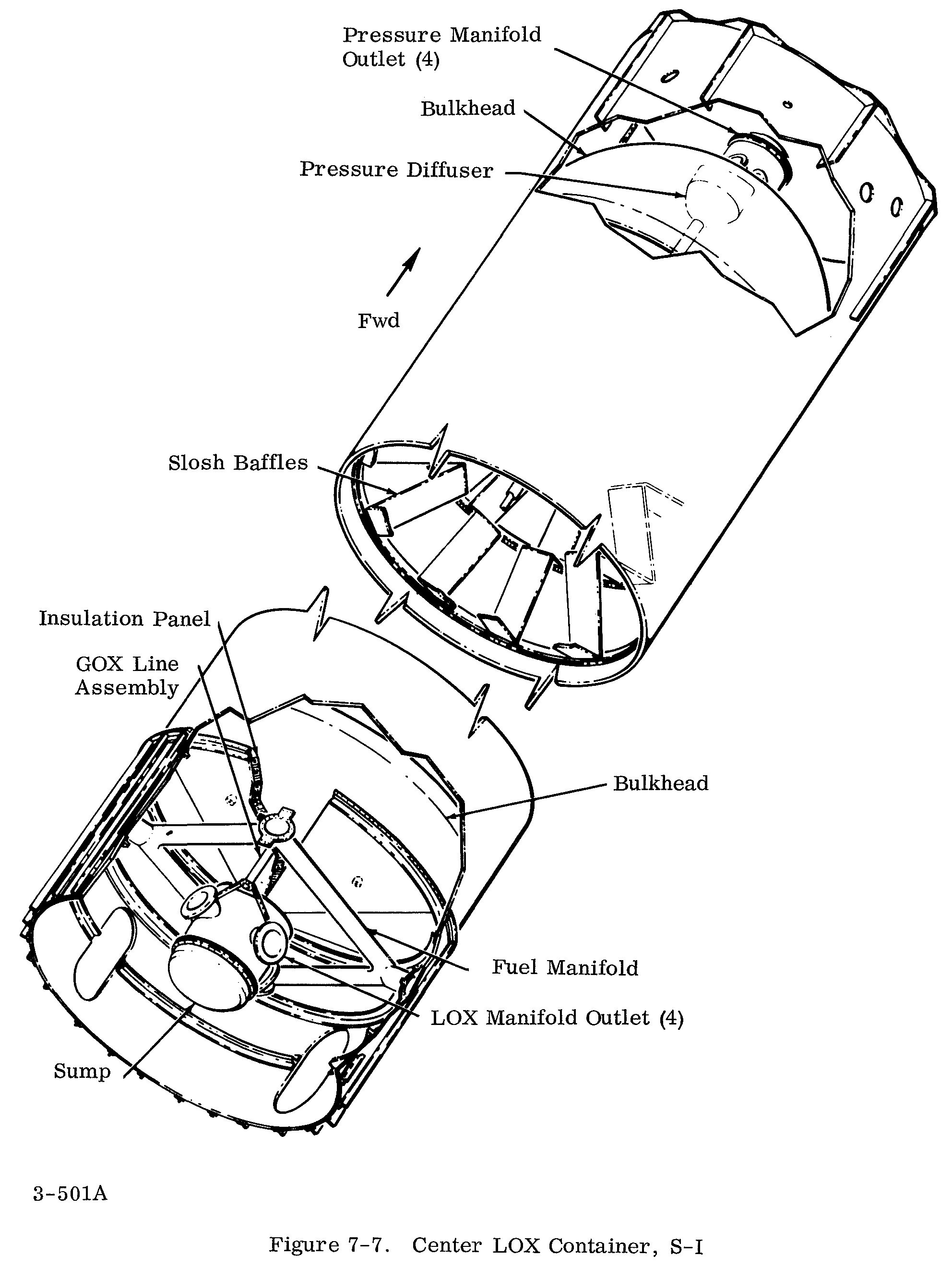
Note the "GOX Line Assembly" just forward of the "Sump" at the aft end of the tank; it is connected to the "Pressure Diffuser" at the forward end of the tank, just aft of the "Pressure Manifold Outlet" (refer also to the "GOX Line" and "Pressurant Diffuser" on my Saturn I Block II Inboard Profile).
Click image for a 1985x2640 pixel version of this image in a new window.
Taken from p. 7-17 (184 in PDF) of Apollo
Systems Description, Volume 2 - Saturn Launch Vehicles.
Extraction and cleanup by heroicrelics.org.
The LOX pressurization system was redesigned for the S-IB stage: Each LOX container had its own vent valve, and a single LOX relief valve was employed.
In addition to the Saturn Technical Information Handbook, Volume II and Apollo Systems Description, Volume 2 - Saturn Launch Vehicles, I also drew information from the Saturn SA-1 Flight Evaluation and the Results of the Fifth Saturn I Launch Vehicle Test Flight SA-5.