
Saturn I Block I Profile
Diagrams of the Block I S-I stage.
SA-1 Through SA-4 System Description, the document from which these diagrams were taken, is a very early document -- dated 2 April 1959, only 7½ months after the Saturn program was authorized, nearly a year before the first test firing of the SA-T stage, and two and a half years before the first Saturn flight. The document itself states that it "is preliminary and subject to change and addition ... The information contained herein is for general information only and should not be used as a final design criteria." Some of the items in these drawings did not make it to the final vehicle configuration:
- The document refers to "Booster Recovery Equipment:" "The recovery equipment consists of parachutes and retro-rockets. The parachutes are packaged in the structure at the top of the booster. Retro-rockets are attached to the thrust frame outriggers at the base of the booster. Recovery is intended for the boosters for SA-1 and SA-2." Of course, no such recovery equipment ever flew. Similarly the first stage diagram shows Recruit solid-fuel rockets, apparently part of the first stage recovery equipment.
- Section A-A states that 51 nitrogen spheres (for fuel tank pressurization) were required; the Block I S-I stage used only 48 such spheres. This is the only document I've ever seen which references 51 triplex spheres, but since reading this I have seen several assembly and testing photos of the SA-T static test stage which do have 51 triplex spheres; I'm not certain when this configuration was changed to the more familiar 48. Note that, as I write this, the two photos showing the SA-T stage on the way to the Static Test Tower are mirror image (note that the driver of the truck is sitting on the right, compare the position of the extra triplex sphere to the photo showing the stage being hooked up to the truck, or zoom in and note the backwards lettering).
- The base detail states that there are two short cable mast disconnects at Position I; on the final vehicle configuration, there was one short cable mast at Position II and another at Position IIII (or Position IV).
- The base detail states that LOX replenishing is located on a thrust frame outrigger. I have read no specific documentation for the Block I S-I, but for the S-IB stage, the LOX replenishing coupling is located on the aft end of the vehicle, on the heatshield, next to one of the water quench lines.
- The overall profile states that aspirators were initially considered for the inboard engines, as well as the outboard engines. This contradicts what I have read about the design considerations for turbine exhaust.
Here, then, are the diagrams. All were taken from a barely-legible original copy and required reconstruction and painstaking clean-up.
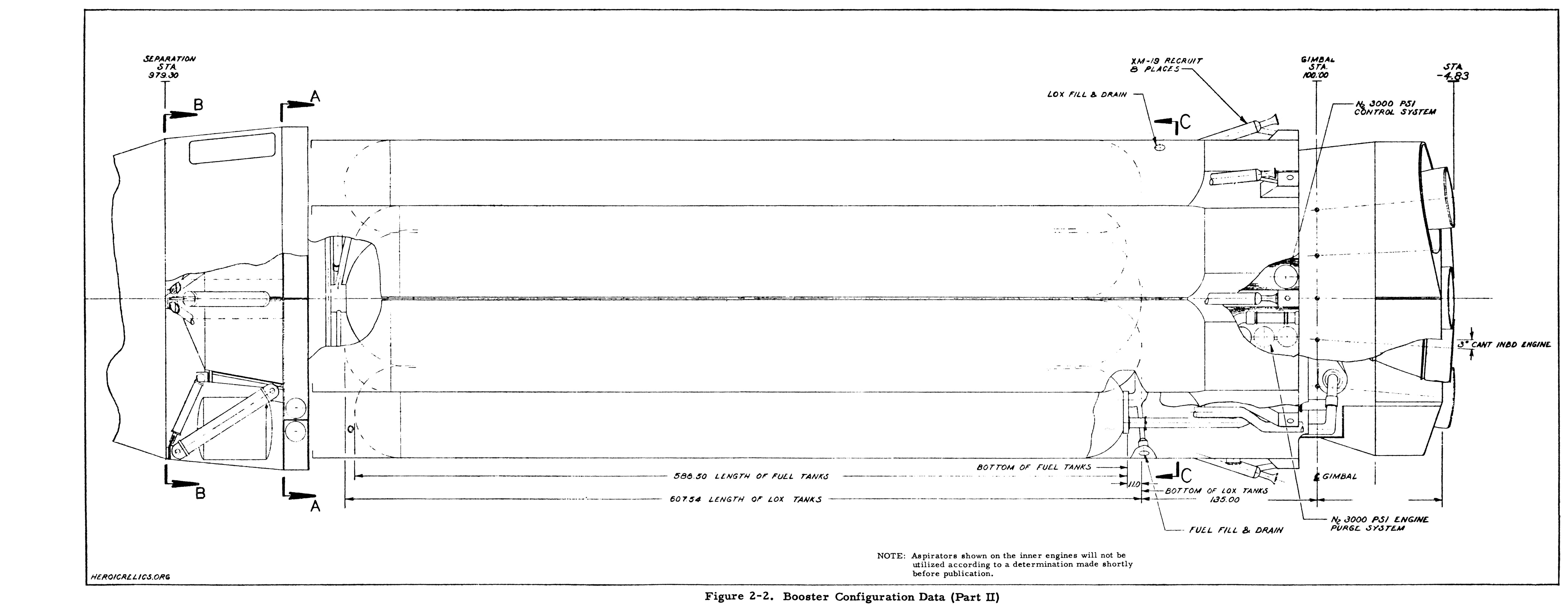
Overall stage diagram. Section A-A, Section B-B, Section C-C, and a view of the base appear below.
Note that this diagram shows 8 XM-19 Recruit solid-fueled rockets at the aft end of the propellant tanks; these were meant to slow the stage's descent during recovery. It also mentions aspirators on the inboard engines. Neither of these features were representative of the final vehicle configuration (although if you zoom in on the S-I stage model in this famous picture of Wernher von Braun, you can see Recruits mounted around the thrust structure).
Click image for a 5790x2250 pixel version of this image in a new window.
From "SA-1
Through SA-4 System Description". Located in the Saturn V Collection, Dept. of Archives/Special
Collections, M. Louis Salmon Library, University of Alabama in Huntsville.
Scan, reconstruction, and cleanup by heroicrelics.org.
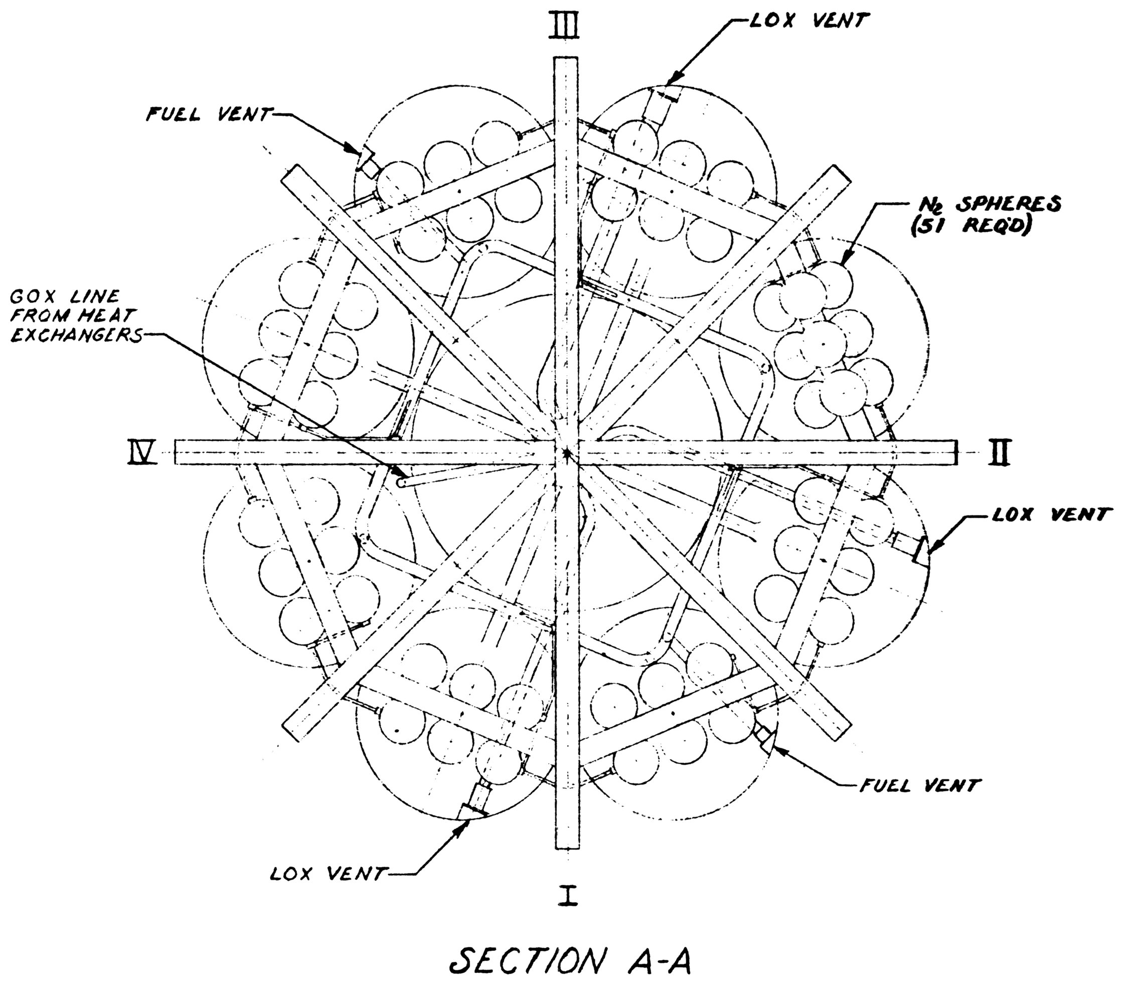
Section A-A, from the profile above. This section, forward looking aft, shows the spider beam, fuel system pressurization (including triplex spheres and fuel system vent), GOX line from heat exchanger (attached to fuel tank no. 4), and lox vent and relief valves (at Positions I and II, labelled "LOX vent" in this diagram).
Note that this diagram shows 51 nitrogen spheres, which is not representative of the final vehicle configuration.
Click image for a 2241x1961 pixel version of this image in a new window.
From "SA-1
Through SA-4 System Description". Located in the Saturn V Collection, Dept. of Archives/Special
Collections, M. Louis Salmon Library, University of Alabama in Huntsville.
Scan, reconstruction, and cleanup by heroicrelics.org.
Section B-B, from the profile above. This section, forward looking aft, shows the second stage adapter and instrumentation canisters. The number of canisters varied slightly from one mission to the next; I believe this configuration reflects SA-1 and SA-2.
Note that this diagram shows recovery gear, which is not representative of the final vehicle configuration.

Click image for a 2406x2330 pixel version of this image in a new window.
From "SA-1
Through SA-4 System Description". Located in the Saturn V Collection, Dept. of Archives/Special
Collections, M. Louis Salmon Library, University of Alabama in Huntsville.
Scan, reconstruction, and cleanup by heroicrelics.org.
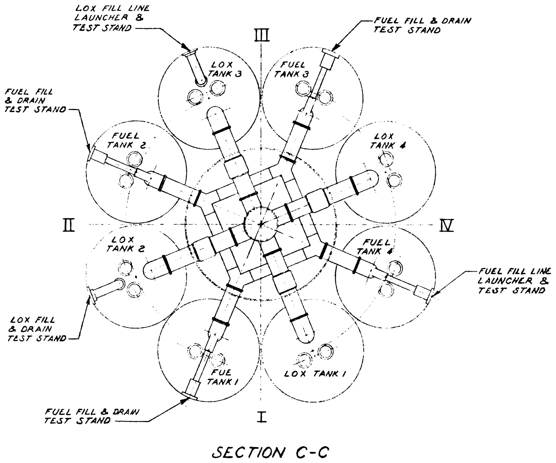
Section C-C, from the profile above. This section, aft looking forward, shows the fuel and LOX manifolds (used to interconnect the four fuel tanks and the five LOX tanks, respectively) and the tank fill and drain connectors. At the test stand, each fuel tank and two of the LOX tanks had a fill and drain connector, while at the pad there was a single fuel and a single LOX fill and drain nozzle. The extra connectors at the test stand provided an emergency drain capability in the case of a fire.
The round connectors near the center of each propellant tank represent the engine feed lines; each outer propellant tank supplied propellant for one inboard and one outboard engine.
Click image for a 2309x1922 pixel version of this image in a new window.
From "SA-1
Through SA-4 System Description". Located in the Saturn V Collection, Dept. of Archives/Special
Collections, M. Louis Salmon Library, University of Alabama in Huntsville.
Scan, reconstruction, and cleanup by heroicrelics.org.
Base view. This section, aft looking forward, depicts a cut-away view of the base of the stage. Note especially how the fuel and LOX lines "wrap around" the engines.
I vaguely remember reading about some early Saturn flights trailing wires from the stage to relay information (perhaps acoustic measurements???) in the seconds around ignition and shortly after take-off; I assume that this is what the "2 trailing cables" item is.
Note that this diagram shows two short cable masts at Position I, retro-rockets on the thrust frame outriggers, and a LOX replenishment fitting on a thrust frame outrigger, which are not (or may not be) representative of the final vehicle configuration.

Click image for a 2188x1993 pixel version of this image in a new window.
From "SA-1
Through SA-4 System Description". Located in the Saturn V Collection, Dept. of Archives/Special
Collections, M. Louis Salmon Library, University of Alabama in Huntsville.
Scan, reconstruction, and cleanup by heroicrelics.org.
I've also prepared three PDFs, containing cleaned-up copies of the original scans:
- A web-resolution PDF for the casual visitor; 640K. View now.
- A 300-dpi version for serious study; 1.4 megabytes. Download now.
- A 600-dpi version for those of you out there with really beefy PCs and like to zoom in to 800%, or want to go to your local copy shop and print up a copy of your own, or even want to blow some drawings up to the size of your wall; 10.9 megabytes. Download now.