Saturn I Block I S-I Fuel Pressurization System
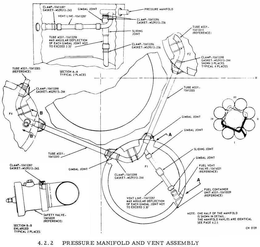
There are four 70-inch fuel (RP-1) tanks on the Saturn I Block I S-I (first) stage, surrounding the 105-inch LOX tank at the center of the cluster (alternating with the four 70-inch LOX tanks). A square-shaped pressure manifold at the top of the tanks connects them to equalize the tank pressure. During flight, the tanks were pressurized from 48 gaseous nitrogen tanks, mounted on the spider beam at the forward end of the stage. These 48 one cubic foot spheres are arranged in groups of three; thus, they are often referred to as "triplex spheres" (as in "duplex," but with three instead of two).
The S-I stage had two fuel vent valves, located on the forward skirts of fuel tanks 1 and 3, which were used to provide venting of the fuel system during fill and drain operations.
Click image for a 2268x2151 pixel version of this image in a new window.
Taken from p. 4.2.4 (p. 75 in the PDF) of Saturn
Technical Information Handbook, Volume II.
Extraction and cleanup by heroicrelics.org.
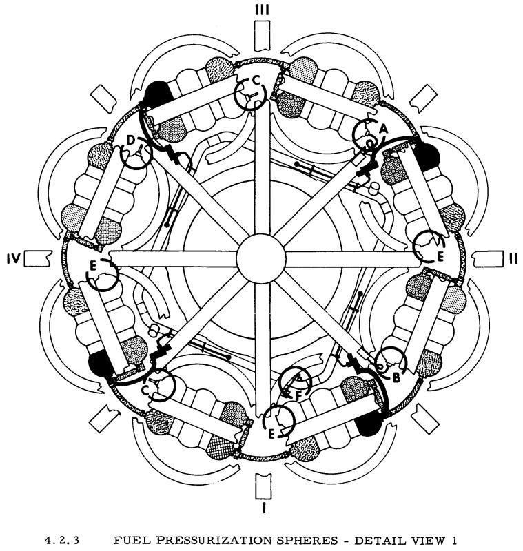
During flight, the fuel tanks were pressurized with gaseous nitrogen supplied from the 48 triplex spheres, as shown in the diagram below. Fuel system pressurization was somewhat complicated: A pressure switch was located in fuel tank no. 1; when this pressure switch sensed a drop in fuel container pressurization, it opened up to four pressurization valves to admit nitrogen into the pressure manifold. The number of valves actually opened to provide pressurization was controlled via a programmed tape which took into account pressure decay in the nitrogen spheres and changes in ambient pressure. Depending upon the mission elapsed time, one, two, or three pressurizing valves were turned off.
Note how the sets of spheres are interconnected with flexible hose. Also note the black tubing in the diagram connecting the spheres to pressurization manifold. (The different colors of the spheres and the lettered circles detail how the tanks interconnect; readers interested in that level of detail are referred to the original source document.)
Click image for a 2088x2202 pixel version of this image in a new window.
Taken from p. 4.2.5 (p. 76 in the PDF) of Saturn
Technical Information Handbook, Volume II.
Extraction by heroicrelics.org.
While I said I wasn't going to go into too much detail regarding how the spheres interconnected, I decided to throw in this diagram showing the flexible hose and common methods of interconnecting the pheres.
Click image for a 1704x2876 pixel version of this image in a new window.
Taken from p. 4.2.7 (p. 78 in the PDF) of Saturn
Technical Information Handbook, Volume II.
Extraction by heroicrelics.org.
The S-I fuel pressurization system was modified for the Block II vehicles, with the 48 spheres 1 cubic foot nitrogen spheres on the spider beam being replaced by two 20 cubic foot spheres located in the forward skirts of tanks F-3 and F-4. It still retained the pressure switch in tank F-1, but this switch now controlled only three (instead of four) pressurization valves. I was able to find specific reference to the fuel vent valves being used to relieve any in-flight overpressurization (which makes sense, but I could find no reference of the Block I fuel vent valves serving this purpose).
The fuel pressurization system was modified again for the Saturn IB vehicles. While two 20 cubic foot spheres in F-3 and F-4 were retained, the medium was changed from nitrogen to helium. Rather than using the pressurization valve scheme of the S-I stage, the S-IB stage used a "sonic nozzle" to control the flow of helium into the pressurization manifold, acting as a "straight blowdown system." The sonic nozzle "limits the flow of helium from the storage spheres into the fuel containers and eliminates the possibility of overpressurization during flight" (OK, "blowdown system" and "sonic nozzle" are a bit beyond my understanding, so I provided direct quotes from NASA documentation). As with the Block II S-I, the fuel vent valves (relocated from tanks F-1 and F-3 in the S-I stage to the forward skirts of tanks F-3 and F-4) were used for in-flight emergency venting (presumably, in case of sonic nozzle failure :-)
In addition to the Saturn Technical Information Handbook, Volume II, I also drew information from the Saturn SA-1 Flight Evaluation, Apollo Systems Description, Volume 2 - Saturn Launch Vehicles, the Results of the Fifth Saturn I Launch Vehicle Test Flight SA-5 (the SA-5 document, also known as MPR-SAT-FE-64-17 or TM-X-56297, was previously available through the NASA Technical Reports Server as Document ID 19650060677; it has subsequently been removed from the NTRS), the Results of the First Saturn IB Launch Vehicle Test Flight - AS-201 (direct link to 11.4M PDF file), and Section V of the Saturn IB Vehicle Handbook - Volume II - S-IB Stage (direct link to 5M PDF file).


