
Block I Saturn I Second Stage Adapter
This is the second stage adapter for the Block I series. It sat forward of the spider beam (the forward structural member to which the propellant tanks were attached) and served as a mount point for the dummy upper stages. It was replaced with the more familiar interstage structure starting with the Block II Saturn I vehicles.
The top portion of the diagram is oriented the way the S-I stage was position during ground handling (i.e., Position I down) and this view is forward facing aft.
Click image for a 2160x2380 pixel version of this image in a new window.
Adapted from p. 120 (p. 137 in the PDF) of the Saturn
SA-1 Flight Evaluation.
Extraction, cleanup, and adaptation by heroicrelics.org.
See also this diagram on the Block I profile.
In addition to serving its structural purpose, the second stage adapter also mounted several antennas and enclosed a number of instrumentation canisters.
The antennas mounted on the second stage adapter are largely the same that were mounted on the antenna panels (the rectangular panels mounted on the tops of the propellant tanks) on the Block II Saturn I and the Saturn IBs.
Click image for a 1575x1125 pixel version of this image in a new window.
Adapted from p. 8 in the PDF (no page number in source document) of the
SA-2
Technical Information Summary.
Extraction, cleanup, and adaptation by heroicrelics.org.
The instrumentation canisters contained batteries, measurement and telemetry equipment, and the guidance system; they are somewhat analogous to the instrument unit introduced with the Block II vehicles and carried through to the Saturn IB and Saturn V. The number of canisters and their content varied slightly from one mission to the next.
Note that in the diagram above, Canister 13 is located between Pos I and Pos II while Canister 16 is located between Pos I and Pos IV, and Canister 14 is located between Pos III and Pos II while Canister 15 is located between Pos II and Pos IV, but in the diagram below the position of the canisters within each set are swapped.
Click image for a 4604x3517 pixel version of this image in a new window.
From Figure 4 (no page number in source document) of the SA-3 Technical
Information Summary. Located in the Saturn V Collection, Dept. of Archives/Special
Collections, M. Louis Salmon Library, University of Alabama in Huntsville,
which also makes this document available
electronically.
Scan and cleanup by heroicrelics.org.
SA-3 Technical Information Summary describes each canister's function:
Canister 12
- ST-124P & Electronics Box
- Guidance Signal Processor - R
- Main Distributor
- Measuring Racks (4)
Canister 13
- Master Measuring Voltage Supply
- Measuring Distributor
- Time Base Selector
- Meas. Rate Gyros (P,Y,R) ±100°/sec.
- Measuring Racks (9)
Canister 14
- Batteries (2); 28vdc
- Inverter (1800 VA)
- Static Inverter (400 VA)
- Power Distributor
- UDOP
- Azusa
- C-Band Radar
Canister 15
- ST-90 & Servo Loop Amplifier Box
- Control Computer
- Program Device J
- Control Rate Gyros (P,Y,R) ±10°/sec.
- Guidance Signal Processor - R
- Control Voltage Supply
- Flight Sequencer & Slave
- Control Distributor
- Command Receivers & Decoders (2)
- Control Signal Processor
Canister 16
- All Telemeter Equipment Except Link 10
(9 telemeter assemblies)
In these line drawings, the canisters don't seem all that large. However, like everything else associated with the Saturn program, these canisters are big:
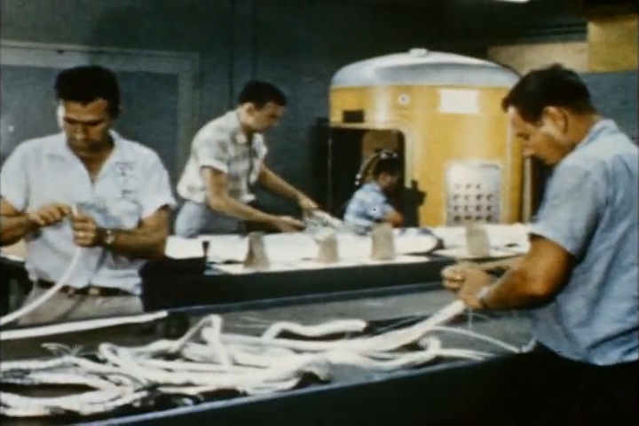
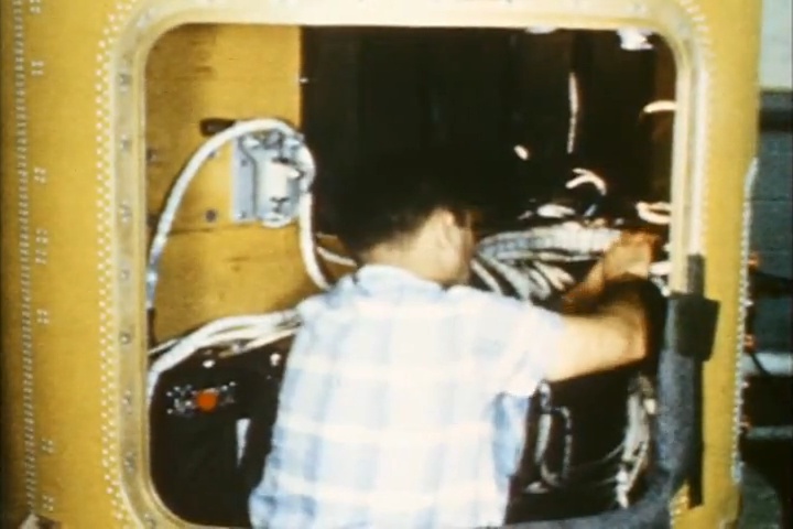
Technicians working on Saturn I Block I instrumentation canisters.
Taken from the NASA film Saturn - A Giant Thrust
into Space".
Extraction by heroicrelics.org.