
Rocketdyne Mark 3 Turbopump
The Rocketdyne Mark 3 turbopump was a real workhorse of the early space race. This turbopump was used on several rocket engines, including the Navaho G26 engine, the S-3D engine (aka LR-79, used on the Jupiter and Thor), the LR-89 (Atlas booster) engine, and the H-1 (used on the Saturn I and Saturn IB).
Even though all of these engines used the "Mark 3 turbopump," with the varying thrust levels of these engines, it would seem that there would have had to have been several variations of this turbopump (and my "Saturn H-1 Engine Design Features" memo certainly seems to support this notion). At the low end, the Navaho engine had 120,000 pounds of thrust. At the high end, the final version of the H-1 had a thrust of 205,000 lb. Even within a single type of engine, the thrust varied; the H-1 was introduced with a thrust of 165,000 lb, but it was uprated three times to 188,000 lb, 200,000 lb, and finally 205,000 pounds of thrust. I've seen a number of Mark 3 TP diagrams, which vary slightly; I don't know if that's an indication of variations in the construction of the TP or whether it's simply because the diagrams were produced for different reasons and therefore highlighted different features.
Turbopump Overview
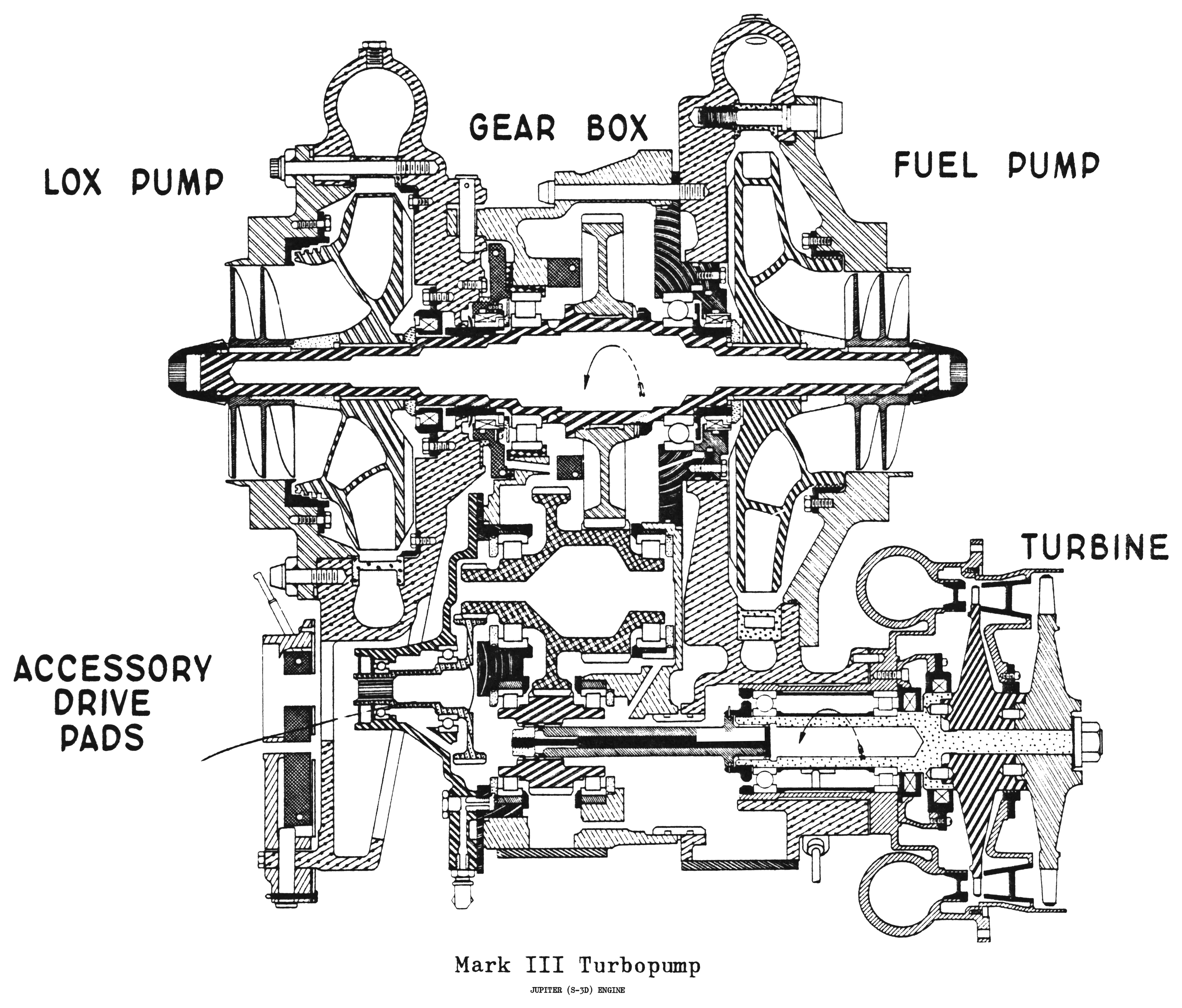
This Mark 3 turbopump diagram is from an S-3D (Jupiter/Thor) engine document:
Click image for a 4406x3757 pixel version of this image in a new window.
From the page 28 of Jupiter (S-3D) Engine Development History, 1957
through 1959, a Rocketdyne document by T.F. Benham dated 5 August 1960.
From the private collection of Dave Christensen
Scan and cleanup by heroicrelics.
Here's a more artistic view of the turbopump cut-away presented above. This was also labelled as a Jupiter version of the Mark 3:
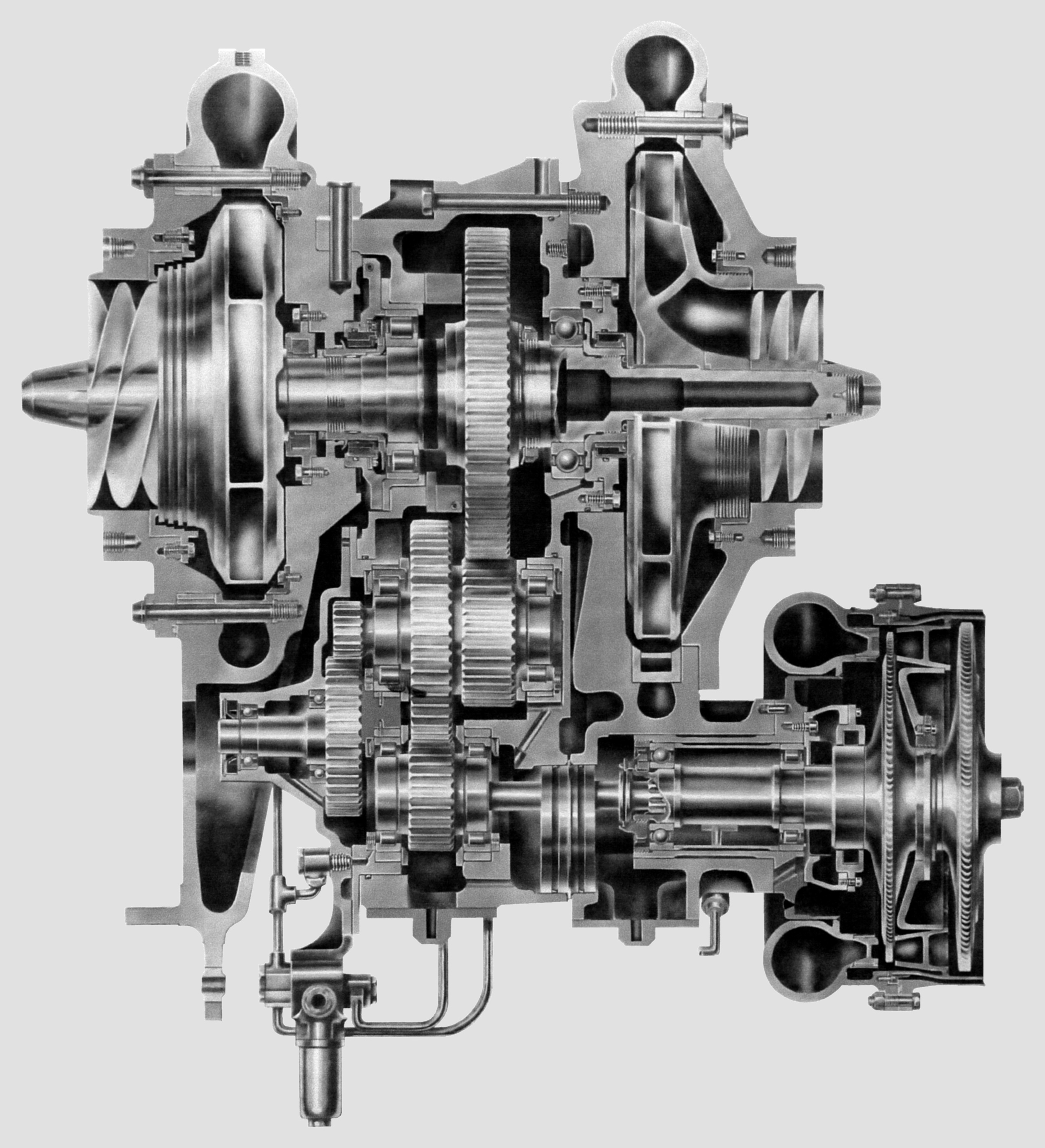
Click image for a 2498x2745 pixel version of this image in a new window.
Scan courtesy Dave
Christensen
Cleanup by heroicrelics.
Here's an exploded view of the Mark 3 installed on an H-1 engine; note the hot gas discharge from the gas generator at upper center and the turbine exhaust hood at lower left:
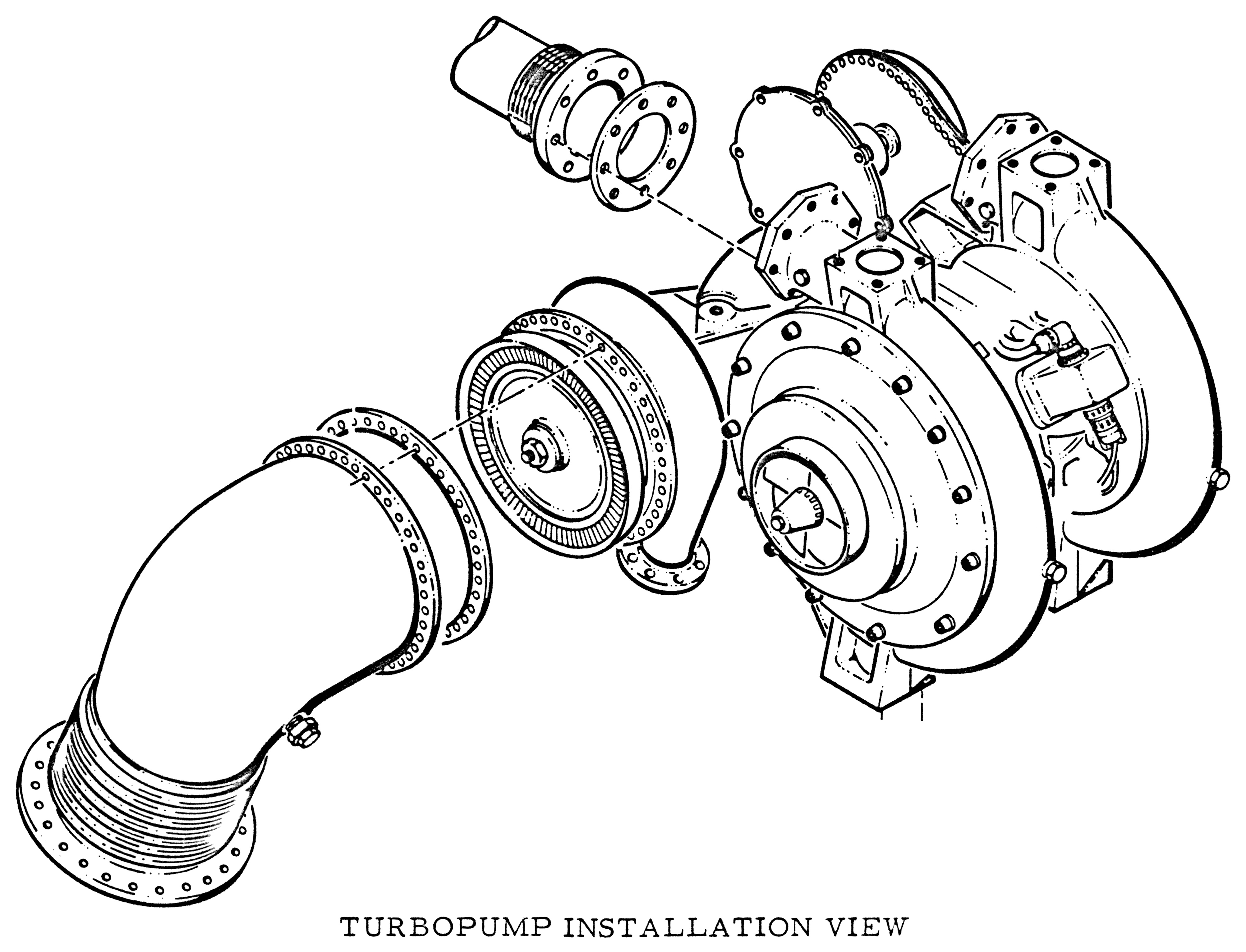
Click image for a 4009x3064 pixel version of this image in a new window.
Adapted from the page ii-22 of the Saturn IB Vehicle Handbook, Volume II:
S-IB Stage. Located in the Saturn V Collection, Dept. of Archives/Special
Collections, M. Louis Salmon Library, University of Alabama in
Huntsville.
Scan, cleanup, and adaptation by heroicrelics.
The turbopump is a turbine-driven, dual-pumping unit consisting of an oxidizer pump, fuel pump, reduction gearbox, accessory drive adapter, and turbine.
On the H-1 engine, the turbopump is mounted on the side of the thrust chamber with the main shaft positioned 90 degrees from the vertical centerline of the thrust chamber; this simplifies the engine system high-pressure plumbing, and provides a high-pressure duct routing with minimum pressure drop.
On other engines using the Mark 3, the turbopump is mounted forward of the gimbal block. This requires longer, flexible high-pressure ducts to carry the high-pressure propellants to the thrust chamber (e.g., on the S-3D).
The outlets of the oxidizer pump and the fuel pump are integral parts of the respective pump volutes. These outlets are attached to the main propellant ducting. During engine operation, the turbopump supplies oxidizer and fuel to the thrust chamber at required pressures and flowrates. The turbopump also supplies the liquid propellant gas generator with the required flow of oxidizer and fuel.
The power for operating the turbopump is provided by the high-speed turbine driven by hot gases from the liquid propellant gas generator. The turbine shaft drives a series of reduction gears which drive the pump shaft, inducers, and impellers. Rotation of the inducer and impeller pumps the propellant by centrifugal force. On the H-1, the turbopump gears and bearings are cooled and lubricated by fuel blended with Oronite via the fuel additive subsystem. On other engines, a separate tank for lubricating oil is provided.
The turbopump incorporates two single-entry, centrifugal propellant pumps mounted back to back, one on each side of the gearbox. The fuel pump is bolted to the gearbox and the oxidizer pump is secured to the gearbox by radially-inserted steel pins. The steel pins allow the oxidizer pump housing to expand and contract during extreme temperature changes without distortion and misalignment. Both pumps are driven by a common shaft and each pump has an axial-flow inducer, a radial-flow impeller, and an integral diffuser. The oxidizer pump and the fuel pump pressurize the propellants for thrust chamber and gas generator combustion. The axial-flow inducers increase the pressure at the impeller inlet and allow a lower net-positive suction head (NPSH). Hollow-vaned, radial-flow pump impellers are used for pumping the propellants. The propellants pass from the inducers into the impeller inlets, which incorporate guide vanes, through the impeller slinger vanes, to stationary diffuser vanes on the pump adapter, and into the pump volutes. The diffuser vanes give uniform distribution of pressure and reduction of fluid velocity around the impellers. Balance ribs are provided on the inboard side of the impellers, for hydraulic balancing of axial thrust on the pump shaft.
Turbine
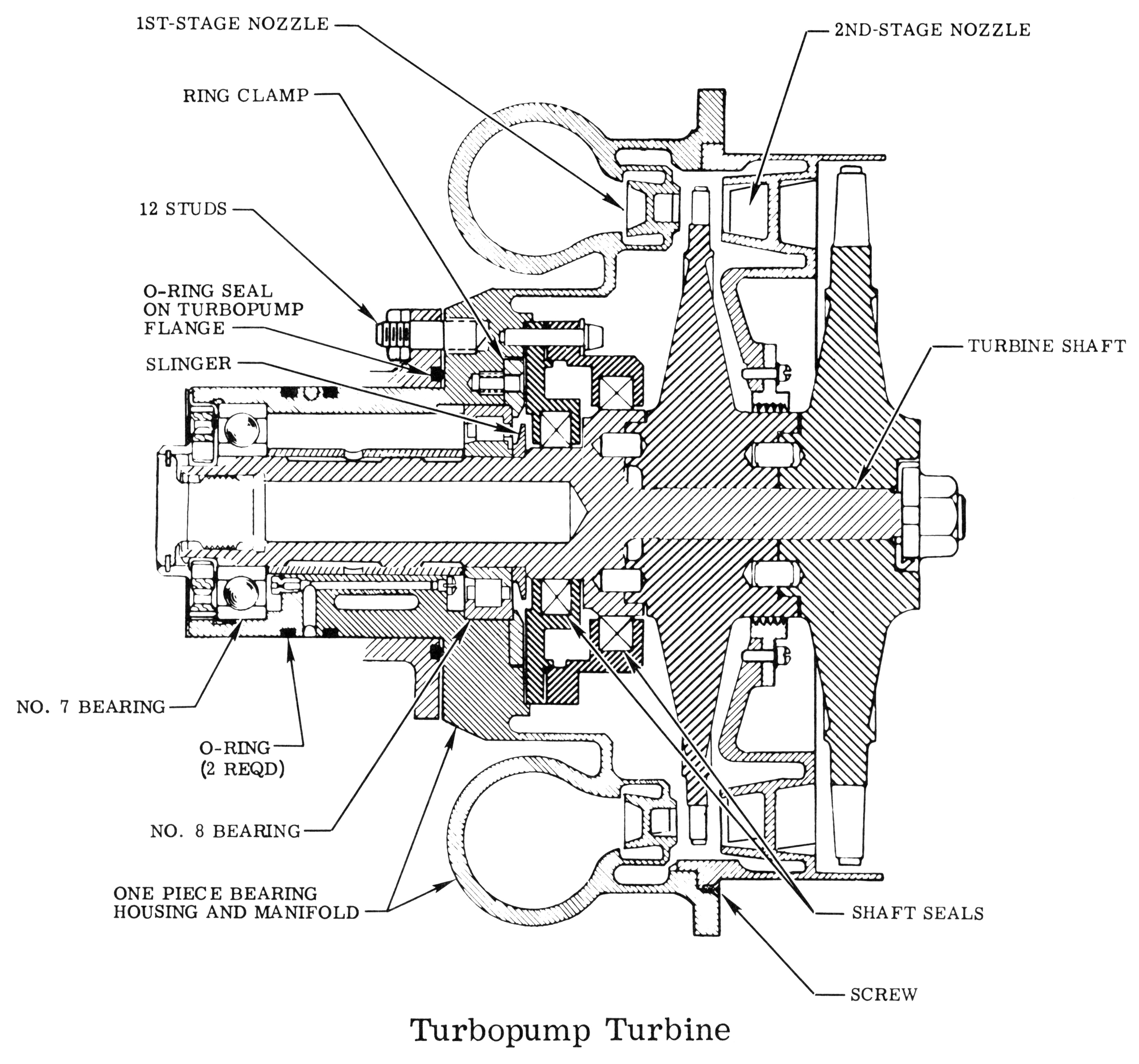
The turbopump turbine is an impulse, two-stage, pressure-compounded unit. The turbine bolts to the fuel pump housing and consists of an inlet manifold, first- and second-stage turbine wheels and nozzles, a turbine shaft, and a splined quill shaft that connects the turbine shaft to the high-speed pinion gear. Carbon ring shaft seals prevent hot gas leakage into the bearings.
Gases from the liquid propellant gas generator enter the turbine inlet manifold, which distributes the gases to the first-stage inlet nozzles. After passing through the first-stage turbine wheel, the gases increase in velocity by passing through the second-stage nozzle and are directed to the second-stage turbine wheel. The gases leave the turbine into the exhaust ducting. The turbine stage seal prevents the gases from bypassing the second-stage nozzles.
Click image for a 3465x3237 pixel version of this image in a new window.
Adapted from the page 1-52 of the H-1 Rocket Engine Models H-1C and H-1D
Technical Manual: Engine Data. Located in the Saturn V Collection, Dept. of Archives/Special
Collections, M. Louis Salmon Library, University of Alabama in Huntsville,
which formerly made this document available as a 14.4
megabyte PDF.
Scan, cleanup, and adaptation by heroicrelics.
I have a number of turbine-related photo sets:
- A turbine from an H-1 engine at in the private collection of Mark Wells
- A turbine from an S-3D engine at the U.S. Space & Rocket Center
- The H-1 engine at the Kansas Cosmosphere has its turbine exposed
- The H-1 engine turbopump removed from Marshall Space Flight Center's Cold Calibration Test Stand has its turbine exposed
- The H-1 engine located near Marshall Space Flight Center's Static Test Stand has its turbine exposed
The bulk of the text on this page was copied, largely verbatim, from H-1 Rocket Engine Models H-1C and H-1D Technical Manual: Engine Data and the Skylab Saturn IB Flight Manual.