
H-1C and H-1D Photos
The H-1 rocket engine came in two basic versions, the H-1C (or inboard) and the H-1D (or outboard) engine.
The basic engines were the same; the difference lay in how the turbine exhaust was disposed of.
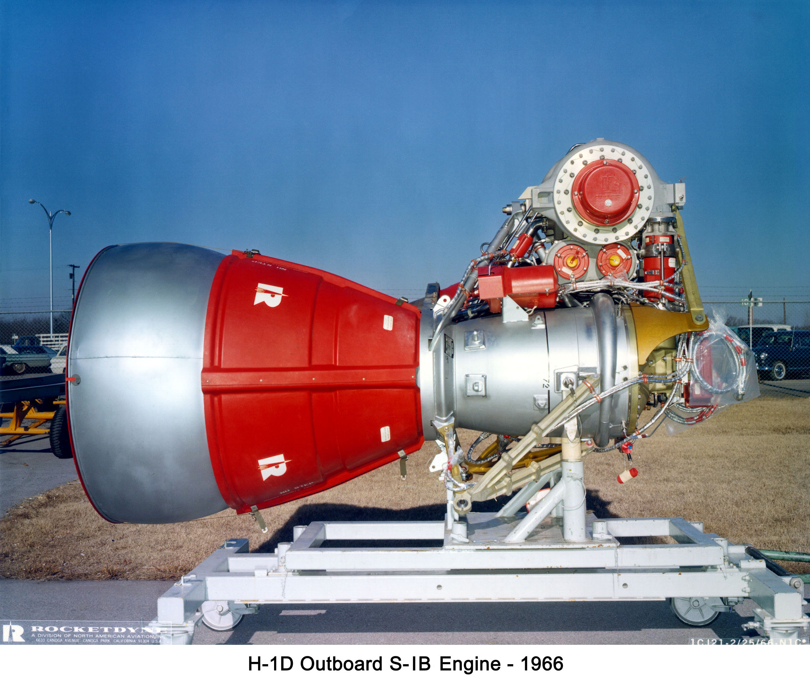
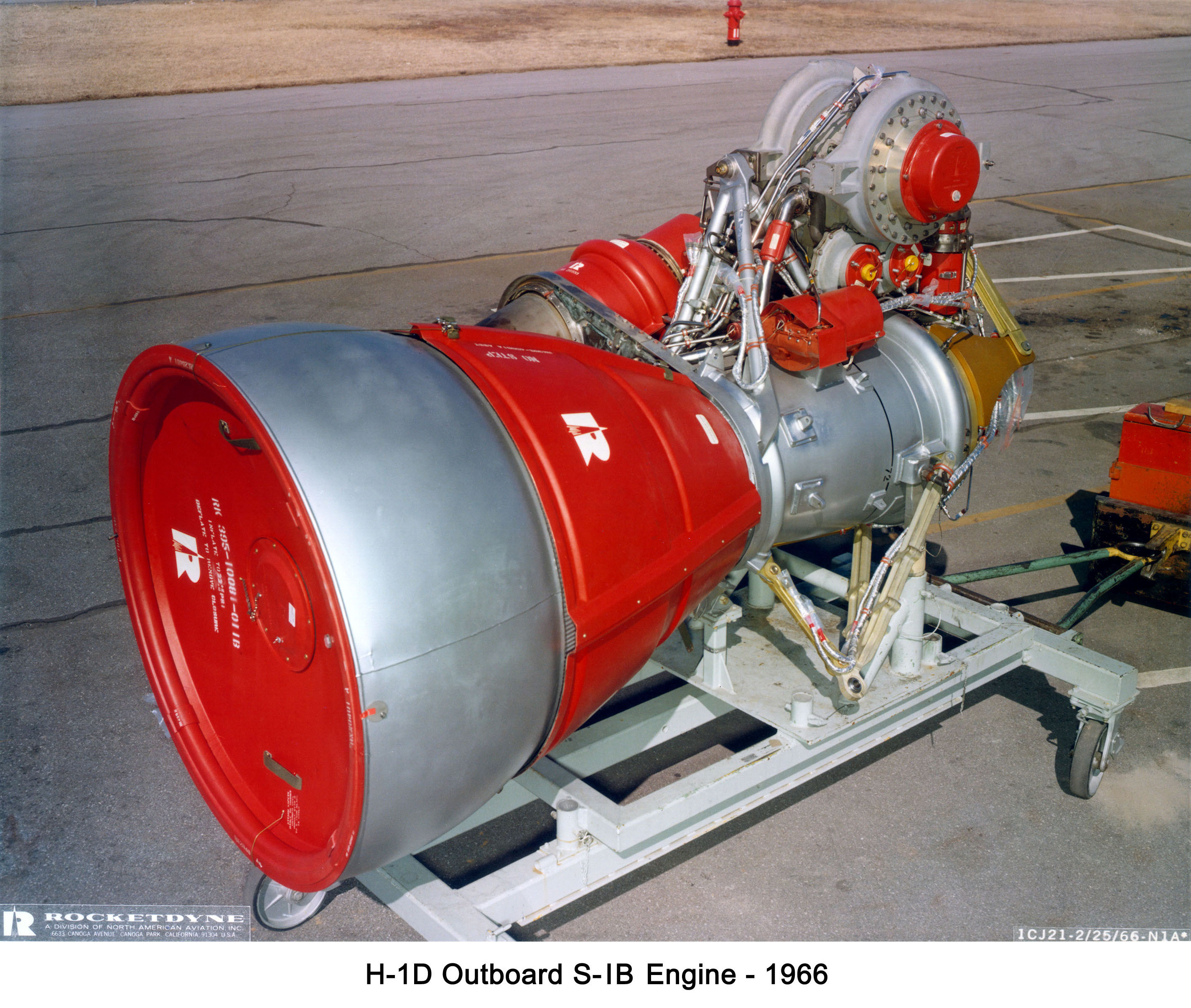
For the H-1D, mounted in the outboard position on a Saturn I or Saturn IB, the turbine exhaust was routed through the engine's heat exchanger and then to an aspirator, a shell around the aft end of the engine and extending past its exit plane. The turbine exhaust was distributed around the periphery of the engine, where it was introduced into the engine's exhaust stream.
Here are three vintage photos of an H-1D engine, clad in its cover and closure assemblies: and
Click image for a 2843x2397 pixel version of this image in a new window.
Photo courtesy Vince
Wheelock.
Click image for a 2850x2413 pixel version of this image in a new window.
Photo courtesy Vince
Wheelock.

Click image for a 2850x2413 pixel version of this image in a new window.
Photo courtesy Vince
Wheelock.
The H-1C was mounted in the inboard position. There were actually two versions of the H-1C; I'm not certain why the second H-1C version wasn't called the H-1E or similar.
On all of the Saturn Is and the first two Saturn IBs which were manufactured (AS-201 and AS-202), the turbine exhaust duct (along with the engine's heat exchanger) was routed to the side of the S-I or S-IB stage's aft skirt. On the first four Saturn Is (the Block I design, SA-1 through SA-4), the turbine exhaust was routed through vaguely "S"-shaped ducts. The remaining Saturn Is (the Block II design, SA-5 through SA-10) and the first two Saturn IBs which were manufactured (AS-201 and AS-202, whose first stages began their lives as "production" Saturn I Block II stages and were intended to have been launched as AS-111 and AS-112), rather than using the bare pipes of the Block I series, placed fairings around the turbine exhaust ducts.
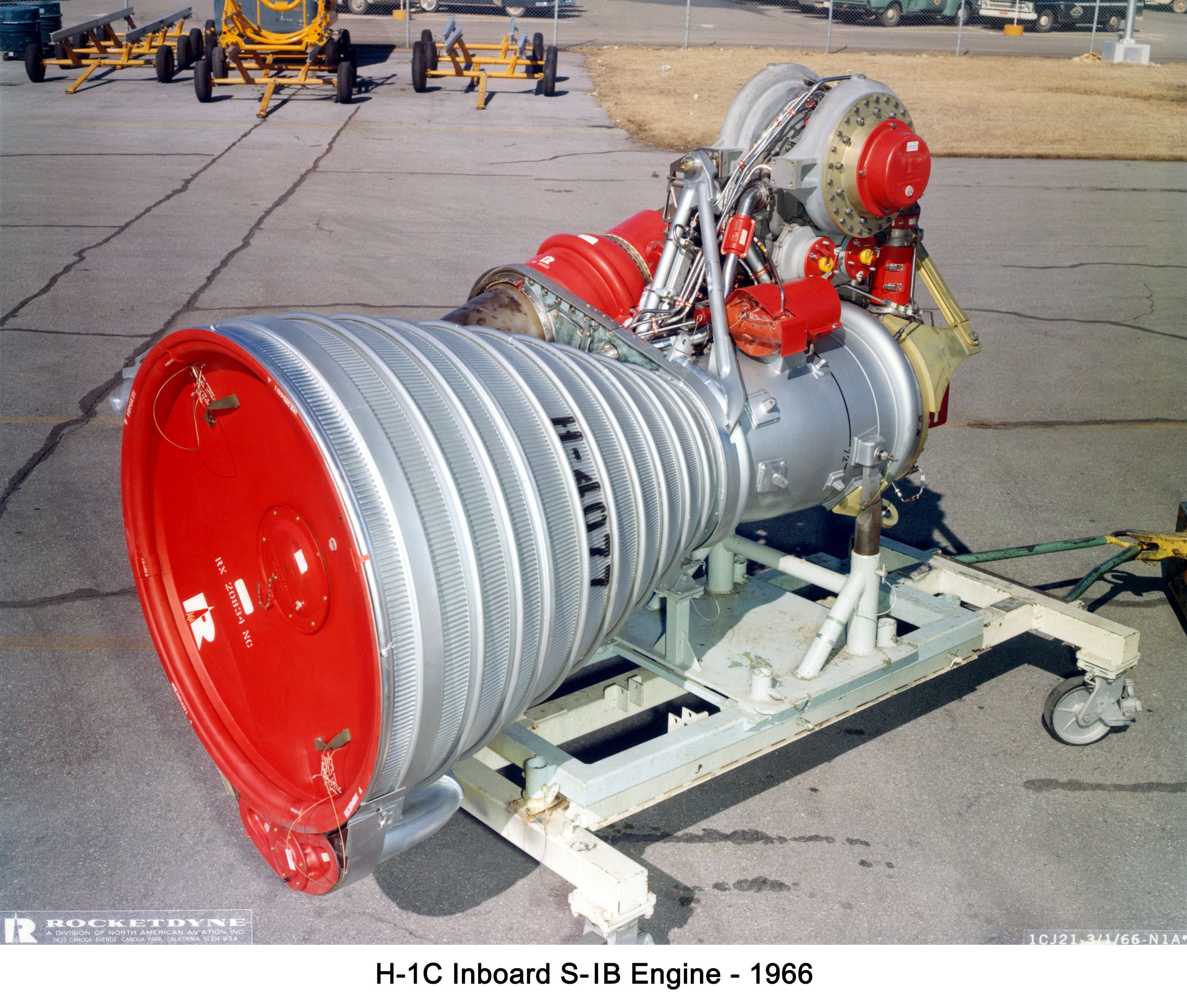
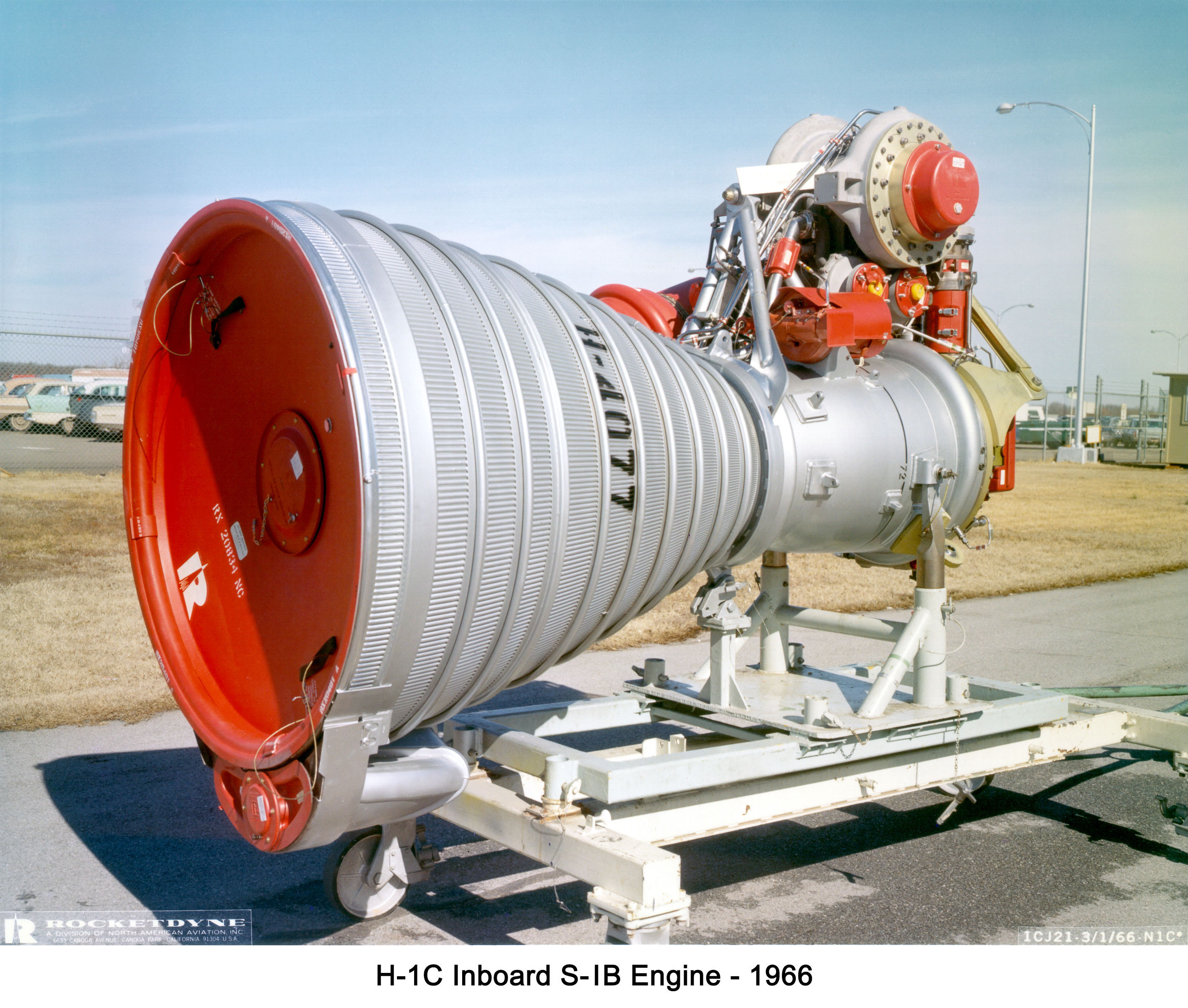
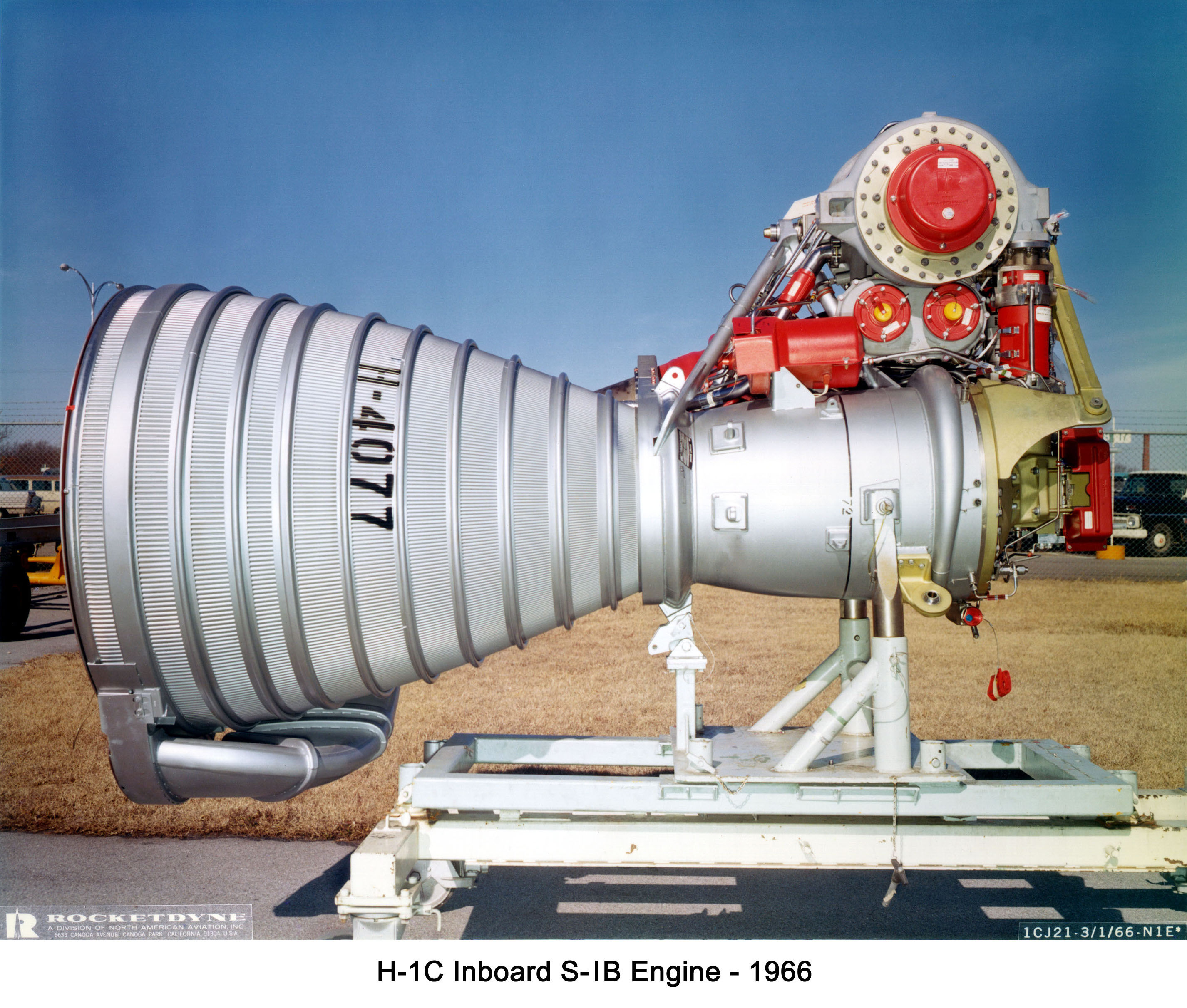
The remaining H-1 engines, flown on the remaining Saturn IB flights, the turbine exhaust was routed through the heat exchanger to partial aspirators or simply turbine exhaust duct (I think I've seen "turbine exhaust duct" used more frequently, but I saw the "partial aspirator" usage first so I tend to use the latter; it's also similar to the outboard engine terminology).
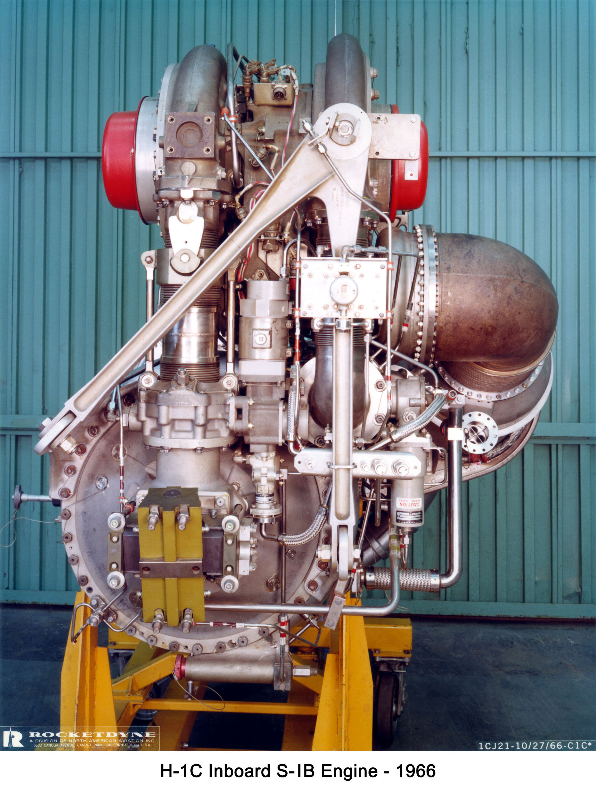
Here are four vintage photos of H-1C engine H-4077; according to Saturn I/IB, this engine flew on AS-208, the third manned Skylab mission. Note the partial aspirator at the 6:00 position of the engine's exit plane in the first three photos:
Click image for a 2837x2408 pixel version of this image in a new window.
Photo courtesy Vince
Wheelock.
Click image for a 2843x2412 pixel version of this image in a new window.
Photo courtesy Vince
Wheelock.
Click image for a 2852x2423 pixel version of this image in a new window.
Photo courtesy Vince
Wheelock.
Click image for a 2261x3009 pixel version of this image in a new window.
Photo courtesy Vince
Wheelock.
This H-1 engine, H-4077, was apparently more photogenic than its peers: In addition to these promotional photos, it also appeared in an H-1 Rocket Engine Fact Sheet.
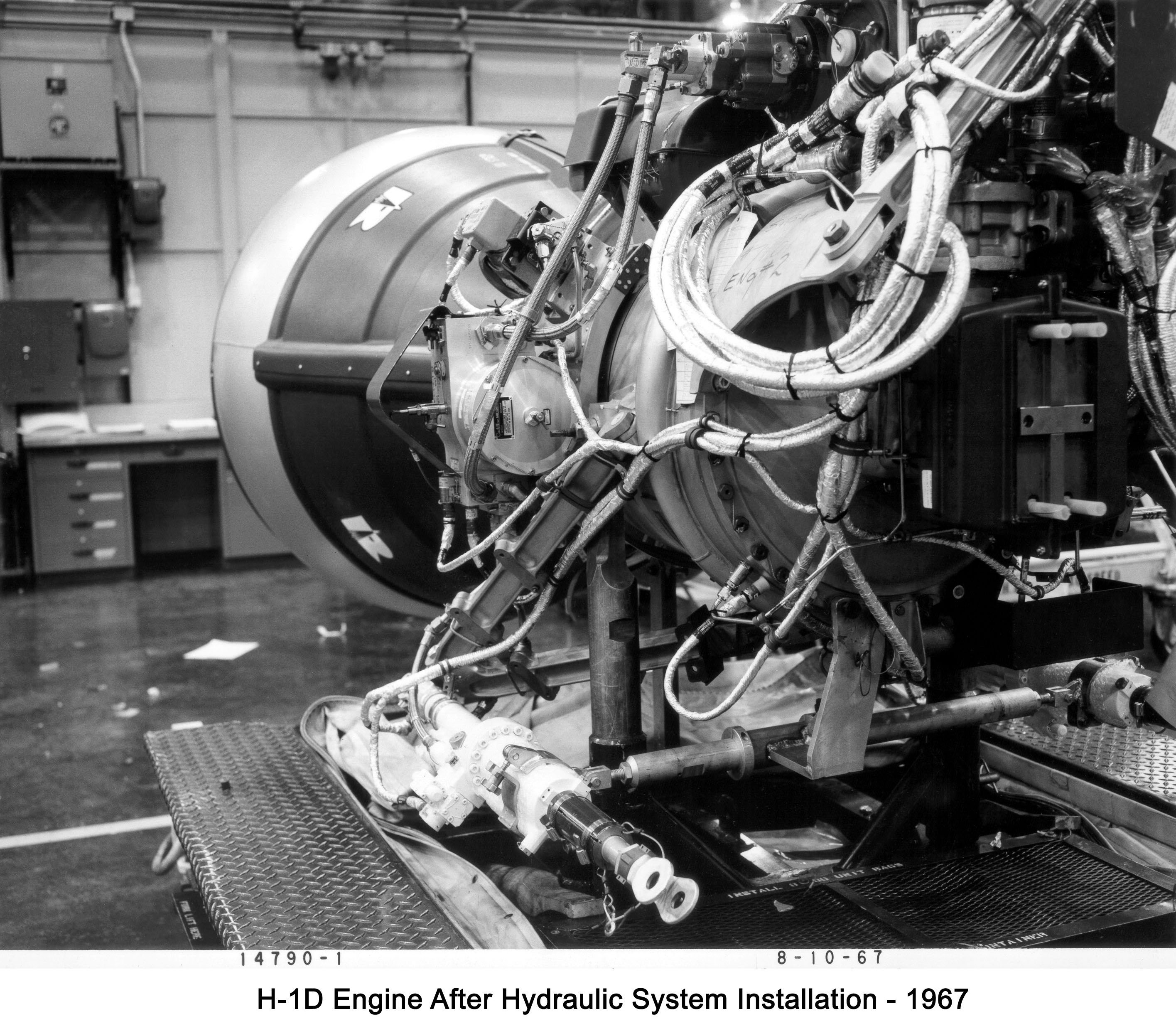
Here's one final vintage photo, an H-1D (outboard) engine with its hydraulic system installed. Note the gimbal actuators at the bottom of the photo:
Click image for a 2831x2481 pixel version of this image in a new window.
Photo courtesy Vince
Wheelock.