
Redstone Rocket Engines
(A-6 and A-7)
This page serves as a repository for photos and diagrams of the Redstone A-6 and A-7 engine proper. (For photos and diagrams of the Redstone engine actually mounted in Redstone missiles, see my Redstone missile engine mount page.)
The Redstone family of engines was the first large rocket engine produced by North American Aviation's Propulsion Section to enter service (the Propulsion Section would later become the Rocketdyne Division of North American Aviation). The Redstone engine was derived from NAA's first large rocket engine, one initially designed for the Air Force's Navaho project.
The Air Force called this first Navaho engine the XLR43-NA-1. Internally, NAA referred to the engines by concatenating their thrust with their nominal burn time, and so this engine became the "75-65" (for an engine producing 75,000 pounds of thrust for 65 seconds). The NAA engineers also decided to use their own designation for the engine: As this this was NAA's first large rocket engine, they labelled it the "A" series. NAA consulted Wernher von Braun during the engine's design, and by the time von Braun came to inspect the engine, the engine was on its fourth design iteration, the A-4. von Braun "thought it was just great" that NAA's engine shared the same designation as the V-2 rocket engine ("V-2" was the propaganda name of the missile; the internal development name of the missile was the "Aggregat 4", or simply the "A4"). While the Navaho soon needed a more powerful engine, this engine would be chosen for the Redstone missile von Braun's team was developing at the Redstone Arsenal.
As with the V-2 engine, the Redstone engine was fabricated from steel and featured a double-walled construction; the engine's 75% ethyl alcohol fuel was run through the passage between the walls of the thrust chamber to provide regenerative cooling. Rather than the V-2's 18 burner cups at the forward end of the combustion chamber, the Redstone engine employed a flat-faced injector (with a triplet injector pattern, with two fuel streams impinging on each oxidizer stream), greatly simplifying the engine's plumbing.
Here's a cut-away diagram of the Redstone (A-6 or earlier) thrust chamber assembly:
Click image for a 3631x2955 pixel version of this image in a new window.
From a series of Chrysler Missile lantern slides in the archives of
the U.S. Space & Rocket Center.
Scan and restoration by heroicrelics.
Callouts in this diagram include
- LOX dome
- Injector
- Thrust chamber
- Coolant passage
- LOX inlet
- Pyrotechnic Igniter
- Expansion rings
- Alcohol inlet
This diagram shows a pyrotechnic igniter, which was somewhat common in early hydrocarbon engines. Also known as an igniter cartridge, it consisted of two electrically-fired pyrotechnic squibs with a burn time of 10 seconds. Suspended from the injector by a thin plastic rod screwed into the injector prior to firing the missile, firing the squibs provided the ignition source for the propellants.
Although I have been able to find very little about the Redstone engine ignition sequence, such igniters in general are less than ideal. They must be manually installed prior to each test or launch (I once met a Rocketdyne retiree whose job on the test stand was to crawl into the thrust chamber and install the igniter; he said that he always wore the firing console key on a lanyard around his neck when installing the igniter, to prevent any unfortunate accidents). Additionally, such igniters frequently have metallic enclosures or covers which were broken up by the ignition and ejected from the cartridge. Such debris or pieces of electrical firing wire would be ejected by the combustion, which could on occasion cause damage to the thrust chamber.
Later engine diagrams show an "ignition fuel line", presumably providing a substance to provide a hypergolic ignition, as was common on later engines.
While early Redstone missile development flights used the A-1 through A-4 versions of the engine, the missile entered service with the A-6 and A-7 versions of the engine. Each model in the "A" series had the same basic operational procedures and was designed for the same performance characteristics, the models differing only in the modifications of various components. In fact, all seven models were interchangeable, requiring only minor tubing modifications for mating the engine to the missile.
Between the A-6 and A-7, a major engine configuration change was made: Rather than two fuel lines extending from the fuel side of the turbopump to the fuel inlet connection at the base of the thrust chamber, the A-7 had a single fuel line. (Note the two alcohol inlets depicted in the diagram above, at the 10:00 and 4:00 positions.) This photo clearly shows the two fuel lines of the A-6 engine:
Click image for a 1751x2841 pixel version of this image in a new window.
Photo courtesy Vince
Wheelock.
Restoration by heroicrelics.
And an engine diagram depicting the two fuel lines of the early Redstone engines; this diagram also includes various engine dimensions:
Click image for a 1563x1378 pixel version of this image in a new window.
From my A-6 Engine Specifications data
sheet.
Cleanup by heroicrelics.
Dimensions noted in this diagram include
- Length of the thrust chamber proper, from the exit plane to the bottom of the LOX dome: 63.70".
- Length of the engine which extends aft from the center unit (i.e., from the exit plane to the top of the engine mount strut flanges): 101 21/32".
- Distance from the top of the engine mount strut flanges to the center of the peroxide tanks: 13 5/32".
- Overall length of the engine, from the exit plant to the forward-most point of the peroxide tanks: 125 9/16".
- Distance from the center of the engine to the outer-most point of the peroxide tanks: 24 1/8".
- The circle inscribing the engine mount strut flanges: 66.786" diameter B.C. (bolt circle).
A second diagram depicting the A-6-style Redstone engine:
Click image for a 2969x3043 pixel version of this image in a new window.
From page 411 of History of Liquid
Propellant Rocket Engines.
Scan and cleanup by heroicrelics.
Oddly, this diagram measures the length of the thrust chamber at 64.75", 1.05" taller than the previous diagram.
Callouts in this diagram include
- Hydrogen peroxide tank
- Turbine discharge volute
- Oxygen pump inlet
- Fuel pump inlet
- Electrical control box
- Oxygen valve
- Heat exchanger
- Thrust chamber with 3 film coolant rings and expansion joints in outer wall.
- Turbine exhaust duct
Although a single peroxide tank is actually drawn, it is of the smaller size and the left-hand diagram shows a bracket on the turbopump for mounting a second tank, so this engine clearly possessed two such tanks.
You'll note that the photo of the A-6 has a single hydrogen peroxide tank, while both diagrams depict two H2O2 tanks. I've never read anything regarding the reason for the difference, and I've never seen a Redstone engine with the two smaller tanks. The only A-6 engine I've seen, at the Udvar-Hazy Center, is equipped with the single, larger tank. All of the A-7s I've seen (other than one modified for a Mercury-Redstone booster) also had the single, large H2O2 tank.
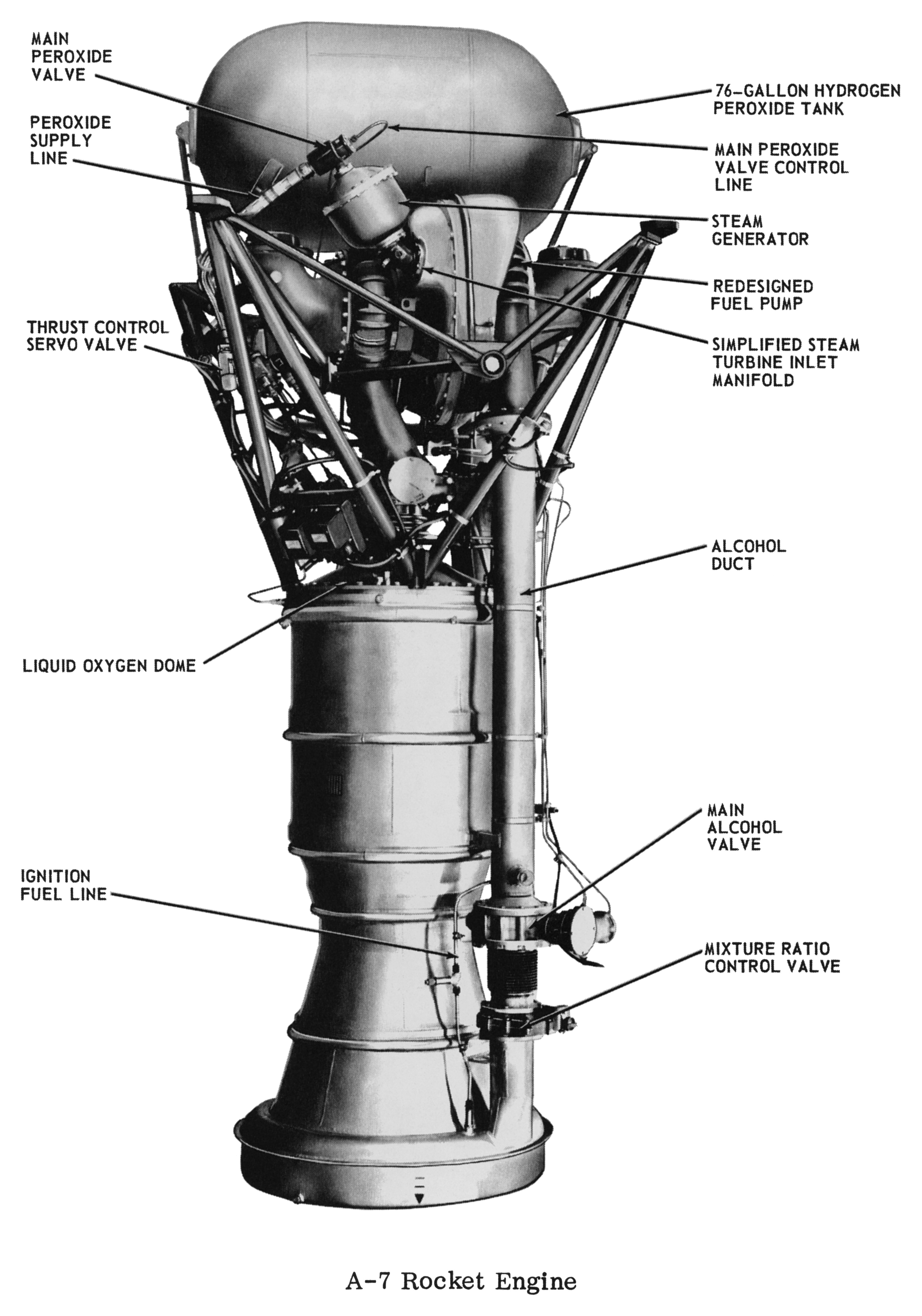
Here's a photo of the A-7, with its single alcohol duct. Comparing the main fuel valve against that of the A-6 above shows that it has been redesigned, and the duct itself has a slightly larger diameter to accommodate the increased fuel flow:
Click image for a 3272x4670 pixel version of this image in a new window.
From p. V-0 of This is Redstone, located in the Dunaway
collection, Dept. of
Archives/Special Collections, M. Louis Salmon Library, University of
Alabama in Huntsville. Available in electronic format from My Army
Redstone Missile Days
Scan and cleanup by heroicrelics.
Callouts in this diagram include
- Main peroxide valve
- Peroxide supply line
- Thrust control servo valve
- Liquid oxygen dome
- Ignition fuel line
- 76-gallon hydrogen peroxide tank
- Main peroxide valve control line
- Steam generator
- Redesigned fuel pump
- Simplified steam turbine inlet manifold
- Alcohol duct
- Main alcohol valve
- Mixture ratio control valve
The Redstone missile served with both the A-6 and A-7 engines. I've been unable to find any documentation as to the number of missiles equipped with which engine. The History of the Redstone Missile System has a table listing the "Development of Different Engine Types" which shows that the cut-over from the A-6 to the A-7 in the development program occurred in June 1958, but that most of the development launches took place with the A-4 engine.
Jim Ryan of My Army Redstone Missile Days, an excellent reference for the Redstone missile and the men who fired and supported it, tells me that the Redstone Block I missiles used by the troops between 1958 and 1960 had the A-6 engine; there were only 19 Block I missiles manufactured by Chrysler (the missile contractor). In mid-1960, the switch was made to Block II missiles, which used the A-7.
The Redstone engine's reported run time varies, from the 110 seconds implied by one of the engine's names, the "NAA 75-110", to 120 or even 121 seconds. I haven't read anything explaining this discrepancy. The engines in missiles converted to the Jupiter-C configuration (for use in qualifying concepts and materials used for the Jupiter missile reentry vehicle) had a run time of 155 seconds. During Project Mercury, the engine's run time was 143.5 seconds.
Although the engine itself produced 75,000 lbs of thrust, the Redstone engine is typically listed as having 78,000 lbs of thrust. The 78,000 figure includes 3,000 lbs of thrust generated by the steam generator exhaust. The engine's fuel is usually reported simply as "75% ethyl alcohol", without mentioning that the remaining 25% was water (as was also the case with the V-2's engine). Although this reduced engine thrust, the water was necessary to keep the combustion temperatures low enough to prevent burn-throughs on the thrust chamber walls.
The engine was called upon to launch heavier payloads, however, in the Redstone's Jupiter-C and Juno I configurations. This challenge was met by a variety of means: The Redstone's propellant tanks were stretched, allowing them to carry additional fuel and oxidizer to support an engine run time of 155 seconds (the engine, not using the main engine's propellants to power its turbine, had to be fitted with an auxiliary peroxide tank to accommodate this extended run time). The fuel was also changed from the alcohol/water mixture to a new fuel called Hydyne, which was a blend of unsymmetrical dimethylhydrazine (UDMH) and diethyltrianine. With the Hydyne, the A-7 produced a higher thrust (83,000 lbs) than with alcohol. The Hydyne had a higher Isp than alcohol and was also more dense, allowing an increased propellant loading. Liquid oxygen was retained as the engine's oxidizer.
Extra thrust was required for Project Mercury as well. The Hydyne fuel was toxic and highly corrosive; this conflicted with the emphasis on safety for the manned spaceflight program, so the engine's fuel was reverted back to the alcohol/water mixture. Project Mercury was ramping up as the A-6 was being phased out of production in favor of the A-7, so the A-7 engine was chosen to prevent a shortage of spare parts. (The A-7 had never been flown with Hydyne, another reason to choose alcohol for the fuel.) A few other minor changes were made to the engine to further improve reliability for the manned program.
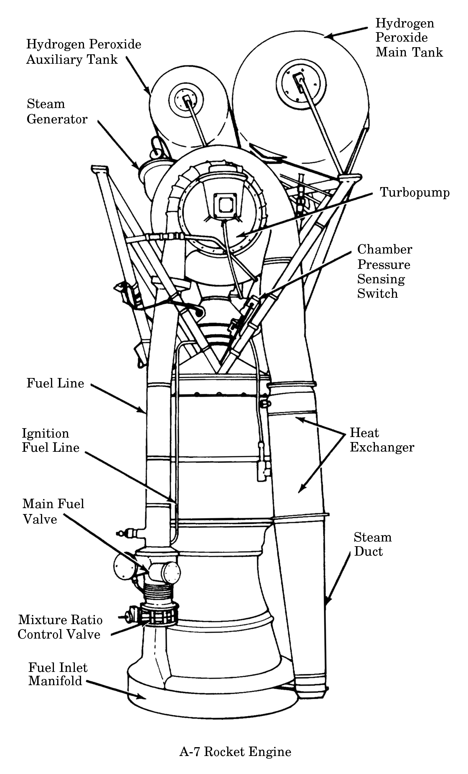
This diagram purports to depict the Project Mercury version of the A-7 engine. You'll note the auxiliary hydrogen peroxide tank, although it is shown in a configuration similar to the "two-tank" configuration shown above. All photos I've seen, both vintage photos and photos I've taken of hardware in museums, show the tank mounted coaxially with the engine, rather than perpendicular to the engine and parallel to the main peroxide tank.
Click image for a 1588x2623 pixel version of this image in a new window.
From page 4-8 (p. 44 in the PDF) of The Mercury-Redstone
Project.
Extraction and restoration by heroicrelics.
Callouts in this diagram include
- Hydrogen peroxide auxiliary tank
- Steam generator
- Fuel line
- Ignition fuel line
- Main fuel valve
- Mixture ratio control valve
- Fuel inlet manifold
- Hydrogen peroxide main tank
- Turbopump
- Chamber pressure sensing switch
- Heat exchanger
- Steam duct
Redstone Engine Data Sheets
I have a data sheet with the specifications of the A-6 engine (strictly speaking, the NAA 75-110), the details of which are reproduced here:
NAA 75-110
The NAA 75-110 rocket engine is a liquid propellant, turbopump fed, single thrust chamber unit, which is rated at a sea -level thrust of 75,000 lb for a duration of 110 sec. The propellants are liquid oxygen and 75-percent ethyl alcohol fed to the thrust chamber by a turbopump unit which, in turn, is powered by the decomposition gases of hydrogen peroxide (75% concentration).
The NAA 75-65 (XLR43-NA-1 Air Force designation), nearly identical to the NAA 75-110, incorporates a single hydrogen peroxide tank, thus limiting the 75,000 lb thrust to a duration of 60 sec.
PDF version: A-6 Redstone Engine Specifications (1 megabyte pdf). Scan courtesy Vince Wheelock. Cleanup and conversion to PDF by heroicrelics.
I have a data sheet with the specifications of the A-7 engine, the details of which are reproduced here:
SYSTEM DESCRIPTION
The Redstone Model A7 powerplant is a turbopump-fed, liquid bipropellant rocket engine which operates at 78,000 lb of sea-level thrust for a nominal duration of 121 sec. The engine is of the single-start type and, since no provision is made for intermediate thrust control, operates only at rated thrust settings.
Main engine propellants are liquid oxygen and denatured 75-percent ethyl alcohol; the turbopump is driven by the exhaust products of decomposed 75-percent hydrogen peroxide. During engine start, liquid oxygen is supplied from the missile main oxidizer tank, and alcohol is supplied from a ground fuel start system.
The double-walled thrust chamber, characteristic of previous models, is also used on the A7. A major change in engine configuration over earlier models is the use of a single fuel line which extends from the fuel side of the turbopump to the fuel inlet connection at the base of the thrust chamber exhaust nozzle. An injector change on 7086, 7087, 7089, 7091, through 7108, 7109a through 7118a, 7119, and subsequent engines replaces the Type 021 injector with a Type 056, an injector of equivalent performance but with a lower pressure drop. Other major system components consist of the turbopump, hydrogen peroxide system, pneumatic and electrical control systems, a propellant feed system, and an engine mount.
Engines 7109a through 7118a, assigned to the Mercury Program, are equipped with an auxiliary peroxide tank to provide the capability of additional engine burning time. This auxiliary tank provides approximately 13 gal of additional hydrogen peroxide.
PDF version: A-7 Redstone Engine System Description (290 kilobyte pdf). Scan courtesy Vince Wheelock. Restoration and conversion to PDF by heroicrelics.
This text on this page incorporates information from the History of the Redstone Missile System, including some passages taken verbatim, or nearly so.