| Prev |
heroicrelics.org U.S. Space & Rocket Center Site Index V-2 Engine (Old Museum) Gallery |
Next |
dsc68437.jpg
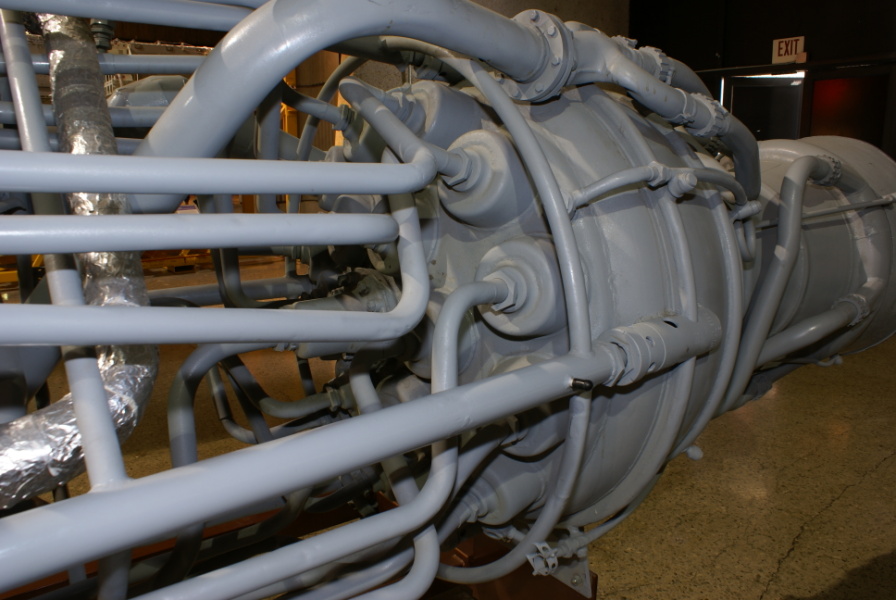
Overall view of the top of the combustion chamber.
Note the liquid oxygen lines, from the LOX turbopump, leading to each of the 18 burner cups on the top of the combustion chamber.
Note the different fitting at the center of the combustion chamber; its line leads to the fuel inlet, forward of the fuel turbopump. I'm not why low-pressure fuel is supplied to the combustion chamber; perhaps to "pre-fill" the space between the inner and outer walls of the combustion chamber prior to turbopump start? There's a simple metal plate in its place on the interior of the interior combustion chamber.
| Time picture taken | Sat Jul 11 14:54:18 2009 |
| Location picture taken |
Space Hall "Old" Museum U.S. Space & Rocket Center Huntsville, AL |
| Prev |
heroicrelics.org U.S. Space & Rocket Center Site Index V-2 Engine (Old Museum) Gallery |
Next |