Redstone A-7 Rocket Engine Steam Generator
The turbopumps in the Redstone missile were powered not by a gas generator as on most later rocket engines, but rather via a hydrogen peroxide-powered steam generator.
The steam generator was at the heart of the steam system, also called the H2O2 system or the hydrogen peroxide system. Hydrogen peroxide, when decomposed rapidly, forms high-pressure, high-temperature steam. In the Redstone missile the peroxide system was used to drive the propellant pumps by means of a steam turbine. The major components of the steam system included a 76-gallon tank, a steam generator, a shutoff Valve, a variable control valve, a pressurizing and venting valve, and an exhaust system.
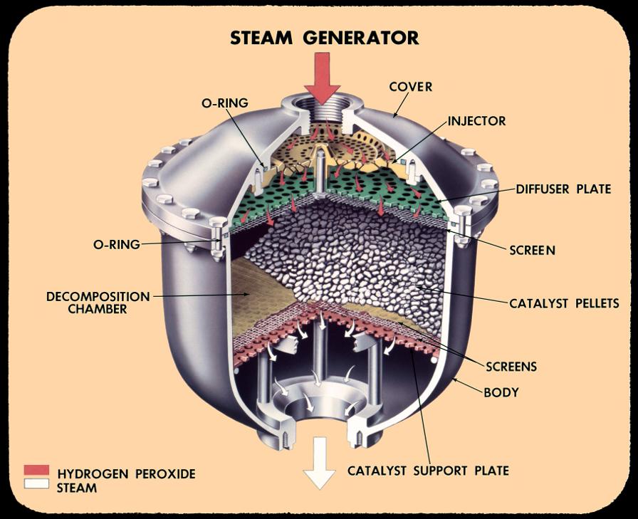
Prior to missile launch, the pressurizing valve would be opened, allowing compressed air to pressurize the H2O2 tank to 550 to 650 psi. The peroxide then flowed through the variable control valve and into the steam generator, also known as the "steam pot". There it was sprayed by the injector through the diffuser plate into the catalyst (potassium permanganate pellets), which rapidly decomposed the peroxide into water and oxygen. This released a tremendous amount of heat, forming high-pressure, high-temperature (700°F) steam. The steam was directed to the turbine, which drove the fuel and LOX pumps. After passing through the turbine, the steam was routed to the heat exchanger, where it vaporized a small amount of LOX (which was then used to pressurize the missile's LOX tank) and expanded the main missile air supply. The steam was then sent over board via the exhaust duct, adding a few hundred pounds of thrust to the missile.
Here's a cut-away diagram of the Redstone (A-7) steam generator:
Click image for a 3631x2955 pixel version of this image in a new window.
From a series of Chrysler Missile lantern slides in the archives of the U.S. Space & Rocket Center.
Scan and restoration by heroicrelics.
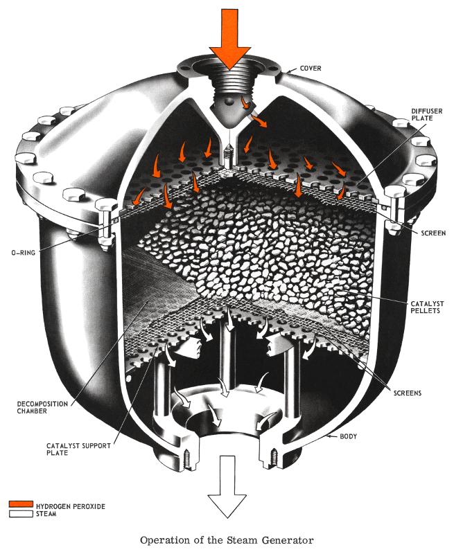
The diagram below is nearly identical to the one above; indeed, I think the two diagrams probably started out their life as copies of one another. However the injector seems to have been redesigned at some point. I don't know whether this smaller, integral injector was found to be inadequate (and thus was redesigned as shown the diagram above) or whether this smaller injector was sufficiently functional, lighter, and/or easier to fabricate (and so was redesigned from the above diagram to produce this diagram).
Click image for a 3897x4760 pixel version of this image in a new window.
From p. VI-16 of This is Redstone, located in the Dunaway
collection, Dept. of
Archives/Special Collections, M. Louis Salmon Library, University of
Alabama in Huntsville. Available in electronic format from My Army
Redstone Missile Days
Scan and cleanup by heroicrelics.
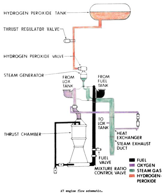
This diagram depicts the overall steam system, including the hydrogen peroxide tank, thrust regulator valve, hydrogen peroxide valve, steam generator, heat exchanger, and steam exhaust duct.
Click image for a 2424x2864 pixel version of this image in a new window.
From p. 18 (page 19 in the PDF) of Memorandum
on Mercury-Redstone Booster Problems.
Extraction and restoration by heroicrelics.
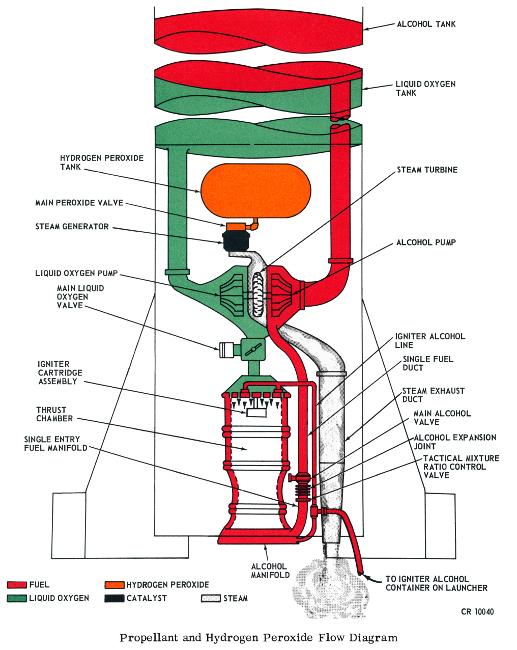
Here the steam system is placed in the overall engine propellant flow system:
Click image for a 4065x5106 pixel version of this image in a new window.
From p. V-2 of This is Redstone, located in the Dunaway
collection, Dept. of
Archives/Special Collections, M. Louis Salmon Library, University of
Alabama in Huntsville. Available in electronic format from My Army
Redstone Missile Days
Scan and cleanup by heroicrelics.
The bulk of the text in this document was taken, sometimes verbatim, from This is Redstone.


