
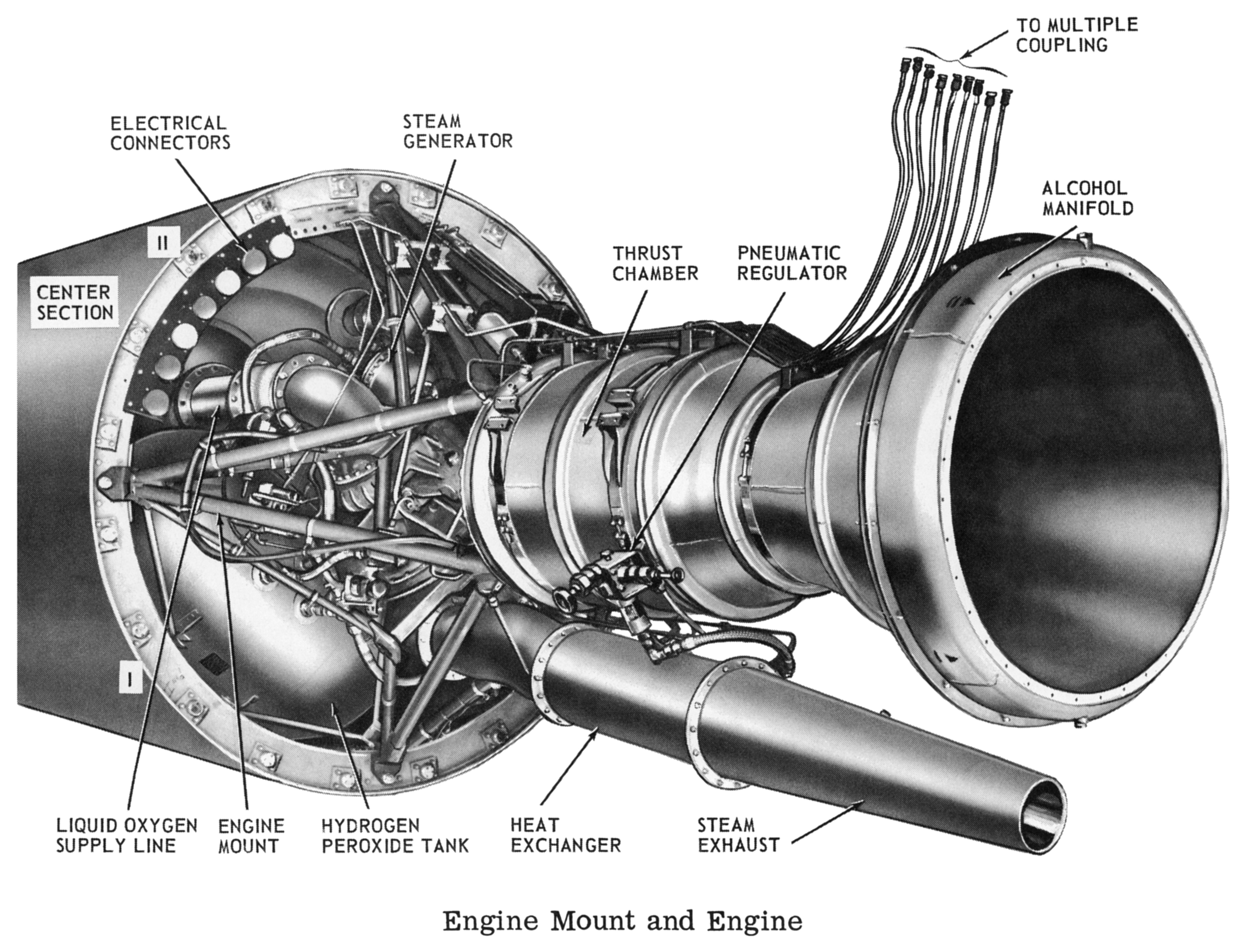
Redstone Missile Engine Mount
Here are some diagrams of the aft end of a Redstone missile with its tail unit removed, showing how its A-7 rocket engine is installed.
Click image for a 3840x2937 pixel version of this image in a new window.
From p. II-10 of This is Redstone, located in the Dunaway
collection , Dept. of
Archives/Special Collections, M. Louis Salmon Library, University of
Alabama in Huntsville. Available in electronic format from My Army
Redstone Missile Days
Scan and cleanup by heroicrelics.
Callouts in this diagram include
- Electrical connectors
- Steam generator
- Thrust chamber
- Pneumatic regulator
- Lines to multiple coupling
- Alcohol manifold
- Center section
- Liquid oxygen supply line
- Engine mount
- Hydrogen peroxide tank
- Heat exchanger
- Steam exhaust
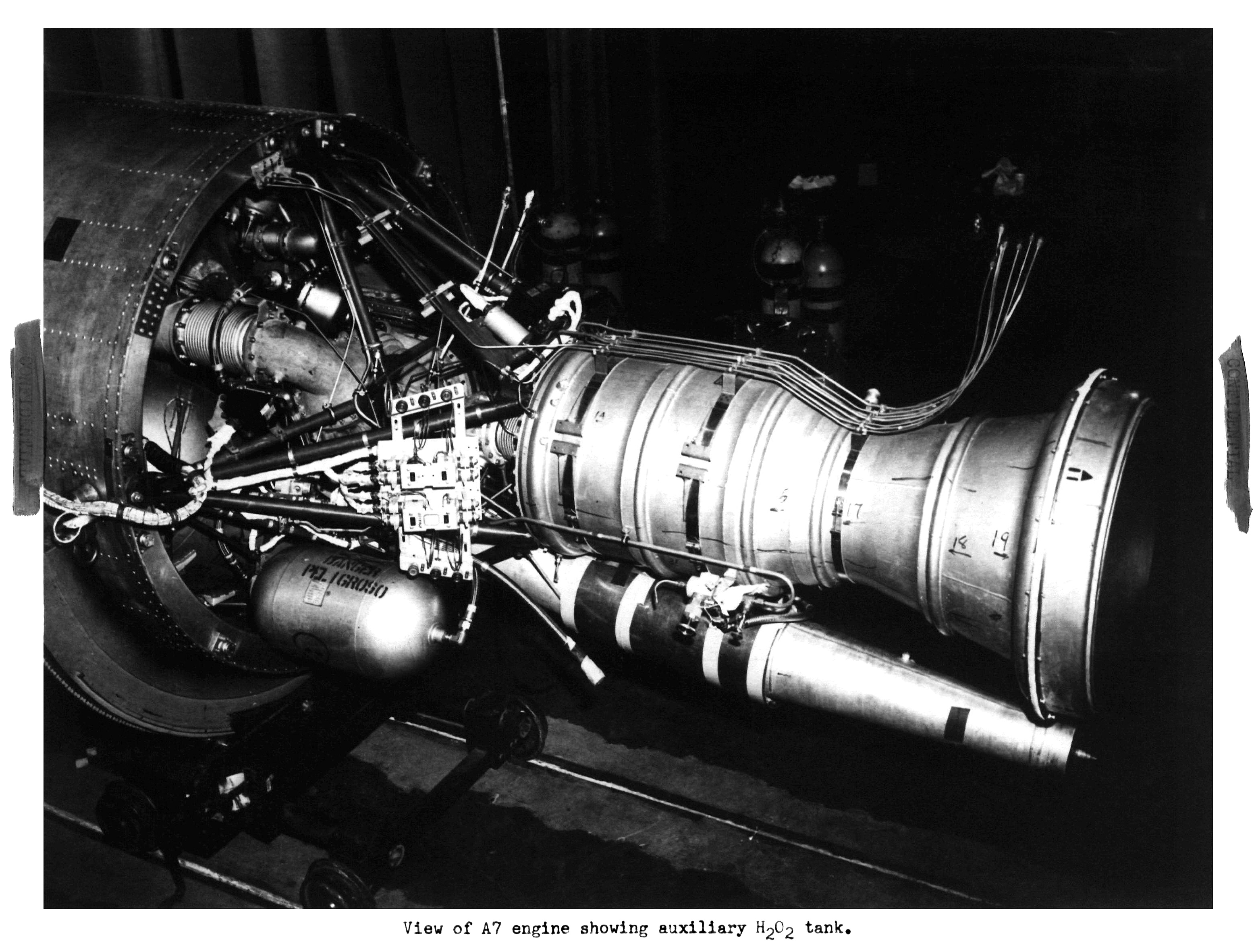
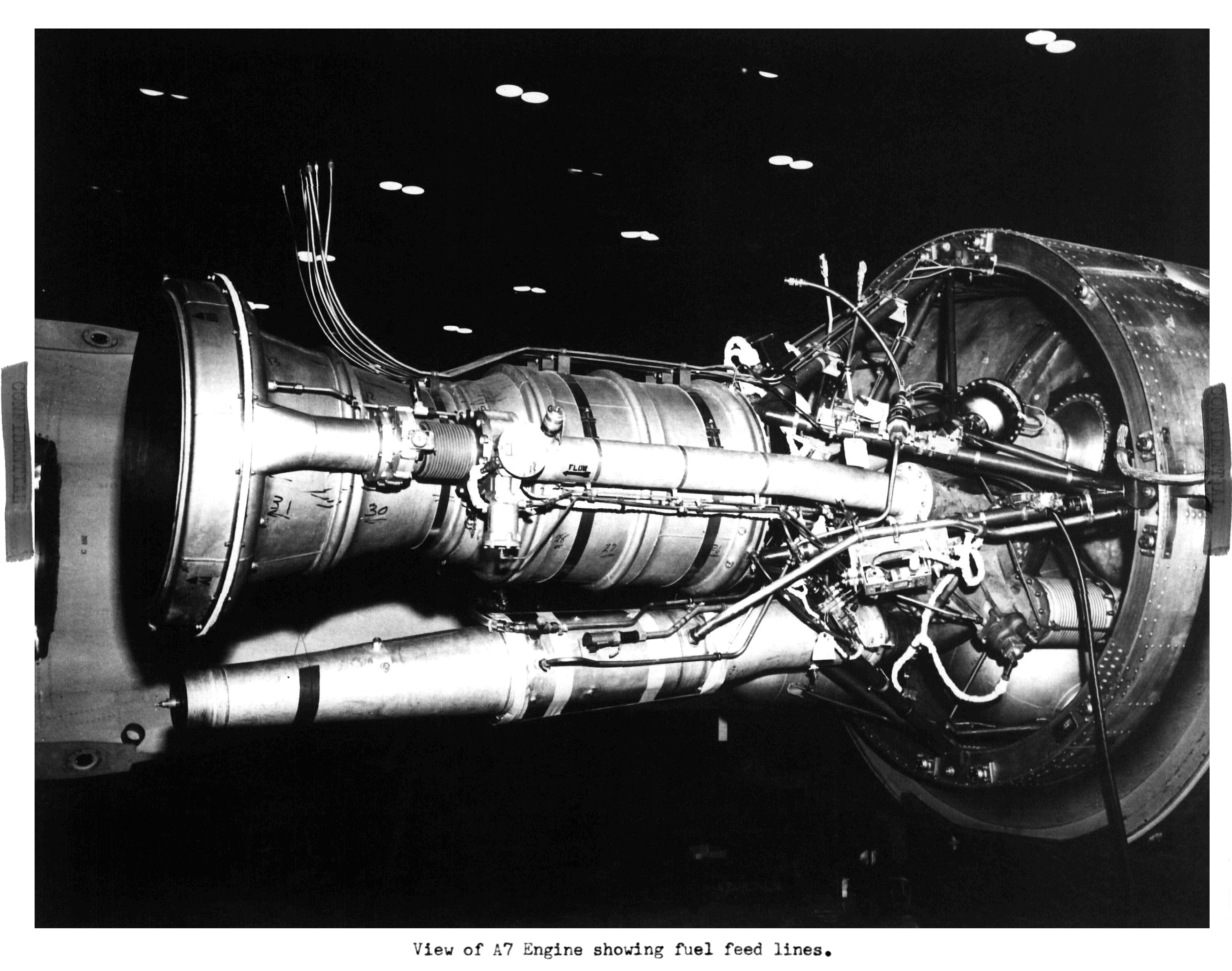
Next are two photos of an A-7 mounted in a Redstone missile modified for Project Mercury. The second photo below has a component labelled "MR-3". Recall that Project Mercury confusingly had both mission names and booster serial numbers beginning with "MR-"; thus, this would seem to be a photo of booster MR-3 (which launched the MR-1A mission).
Recall that, for Project Mercury, the missile's tanks were stretched to hold additional propellants, providing for an engine burn time of 143.5 seconds, 20 seconds longer than the original Redstone missile. As the A-7 used a steam generator powered by a dedicated hydrogen peroxide supply (rather than a gas generator burning the same propellants as the main booster) to drive its turbopumps, it was necessary to install an auxiliary H2O2 tank (visible at lower left in the photo below) to sustain turbopump operation for the extended burn time.
Other than the auxiliary tank, this photo is largely the same as the diagram above, allowing easy identification of its components:
Click image for a 3117x2633 pixel version of this image in a new window.
From p. 25 (page 26 in the PDF) of Memorandum
on Mercury-Redstone Booster Problems.
Extraction and restoration by heroicrelics.
Note the multiple coupling lines which would connect to the multiple pneumatic coupling balcony fittings on the interior of the tail unit. Most engines on display have these lines severed at the bracket on the throat of the thrust chamber, presumably having been cut out of the tail unit to prepare the engine for display.
In the photo below, note the "MR-3" on what would appear to be the tail unit, to the left of and behind the A-7 engine's exit plane.
Click image for a 3026x2385 pixel version of this image in a new window.
From p. 26 (page 27 in the PDF) of Memorandum
on Mercury-Redstone Booster Problems.
Extraction and restoration by heroicrelics.