Redstone Missile Tail Unit
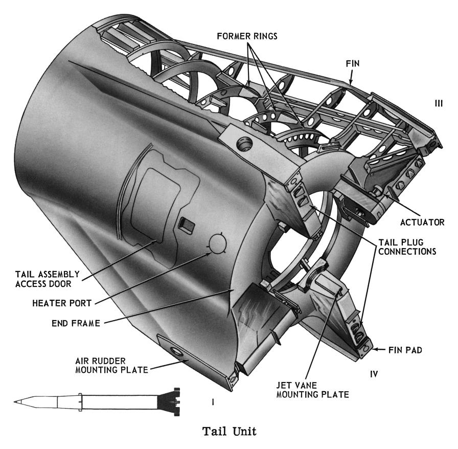
The tail unit, a riveted aluminum structure incorporating four stabilizing fins, was bolted to the center unit after the engine was mounted. Twenty connecting brackets joined the tail unit to the center unit. The center unit, engine, and tail unit were collectively referred to as the thrust unit and the combination was 41 feet 4 inches tall.
Click image for a 3345x3279 pixel version of this image in a new window.
Adapted from p. II-8 of This is Redstone, located in the Dunaway
collection, Dept. of
Archives/Special Collections, M. Louis Salmon Library, University of
Alabama in Huntsville. Available in electronic format from My Army
Redstone Missile Days
Scan, cleanup, and adaptation by heroicrelics.
Callouts in this diagram include
- Former rings
- Fin
- Actuator
- Tail plug connections
- Fin pad
The tail unit served to shroud the engine and provide control surfaces for the first phases of flight. Initially, the missile was controlled by four carbon jet vanes located within the engine exhaust. When the missile reached a velocity sufficient for it to become aerodynamically stable, four air rudders located on the tail unit's fins took over the control function. The jet vanes and air rudders were driven by the same actuator and turned simultaneously, so this transition of control was gradual.
The tail unit also housed electrical components and two sets of high-pressure, triplex spheres which served the pneumatic system. Wiring harnesses mounted to the side of the tail unit connected the electrical system to the tail plugs located on fins II, III, and IV. Two doors on opposite sides of the tail unit allowed access to the tail unit interior.
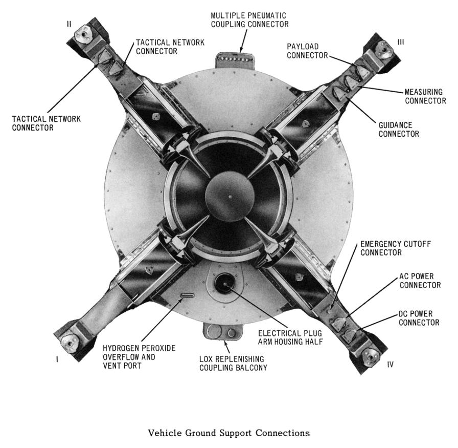
Eight electrical connectors located on the aft face of the fins connected the general electrical network on board the missile with the ground network. After the missile left the launcher at liftoff and the connections were broken, spring-loaded caps covered the ends of the connectors to protect them from the engine's exhaust gasses.
The tail unit had two additional umbilical connections, located 180° apart on the barrel section of the tail unit. One was a LOX replenishment balcony, housing a coupling which connected to the LOX fill and drain valve and was used to top off the LOX tank. The LOX replenishment balcony also had a plate which covered a breather system port, used to circulate air within the tail unit to prevent condensation when the missile was stored.
The other umbilical on the tail unit was the multiple pneumatic coupling balcony. This umbilical provided for ground control of the on-board pneumatic systems, including fill of the high pressure spheres, pressurization of the LOX tank, LOX replenishment control, alcohol bubbling line, pressurization of igniter alcohol tank, LOX vent control, and LOX sensing. It also housed the alcohol injector purge line and the alcohol seal drain line.
Click image for a 3345x3279 pixel version of this image in a new window.
Adapted from p. II-8 of This is Redstone, located in the Dunaway
collection, Dept. of
Archives/Special Collections, M. Louis Salmon Library, University of
Alabama in Huntsville. Available in electronic format from My Army
Redstone Missile Days
Scan, cleanup, and adaptation by heroicrelics.
Callouts in this diagram include
- Multiple pneumatic coupling connector
- Tactical network connector (2)
- Hydrogen peroxide overflow and vent port
- LOX replenishing coupling balcony
- Electrical plug arm housing half
- Payload connector
- Measuring connector
- Guidance connector
- Emergency cutoff connector
- AC power connector
- DC power connector
I'm not certain what the "electrical plug arm housing half" is; it is on the end frame in the location occupied by the steam vent.
Much of the descriptive text on this page was taken from This is Redstone.


