
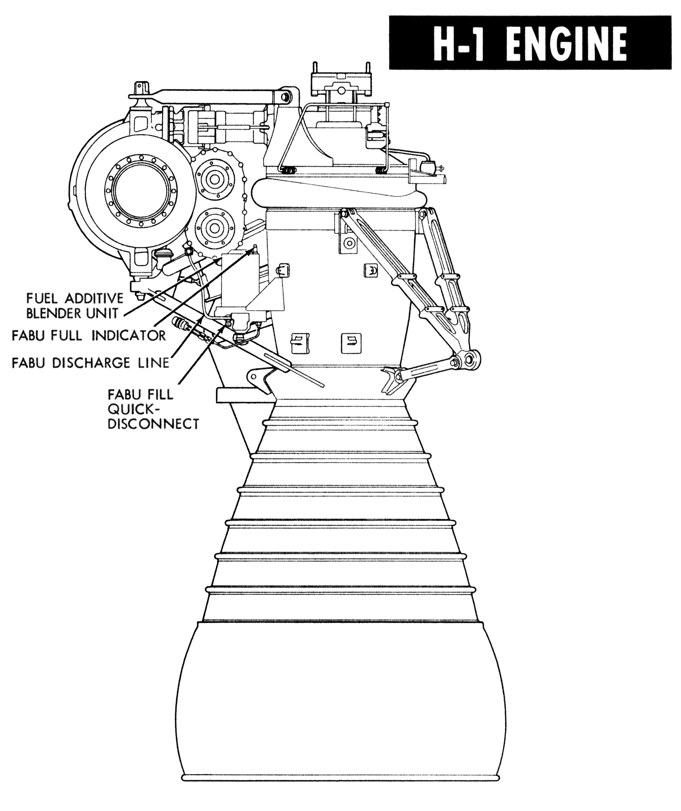
H-1 Rocket Engine Fuel Additive Blender Unit (FABU)
On the H-1 rocket engine, the turbopump gearbox was lubricated and cooled by a combination of the engine's RP-1 fuel and an extreme-pressure additive. A fuel additive blender unit (FABU), mounted on the engine, held this additive and injected it into and mixed it with RP-1 from the fuel pump discharge.

Click image for a 3631x2955 pixel version of this image in a new window.
From a series of Chrysler Missile lantern slides in the archives of the U.S. Space & Rocket Center.
Scan and restoration by heroicrelics.
The H-1 evolved from the S-3D rocket engine, used in the Jupiter missile, with its thrust uprated from the S-3D's 150,000 pounds to 188,000 pounds (with an initial under-rating of 165,000 pounds and eventual upgrades to 200,000 and finally to 205,000 pounds). The H-1 design underwent significant simplification as compared to the S-3D.
One of the areas which underwent a major simplification was the turbopump lubrication system. The S-3D had a 20-gallon, engine-mounted oil tank, the contents of which were used to lubricate the turbopump. The tank on the S-3D was pressurized by gaseous nitrogen and provided enough oil for a 200-second engine run time. In eliminating the oil tank and corresponding pressurizing equipment, plumbing, and control systems in favor of the H-1's FABU, Rocketdyne was not only able reduce weight but was also able to reduce possibility of leakage or contamination, either of which could lead to turbopump failure.
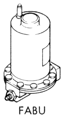
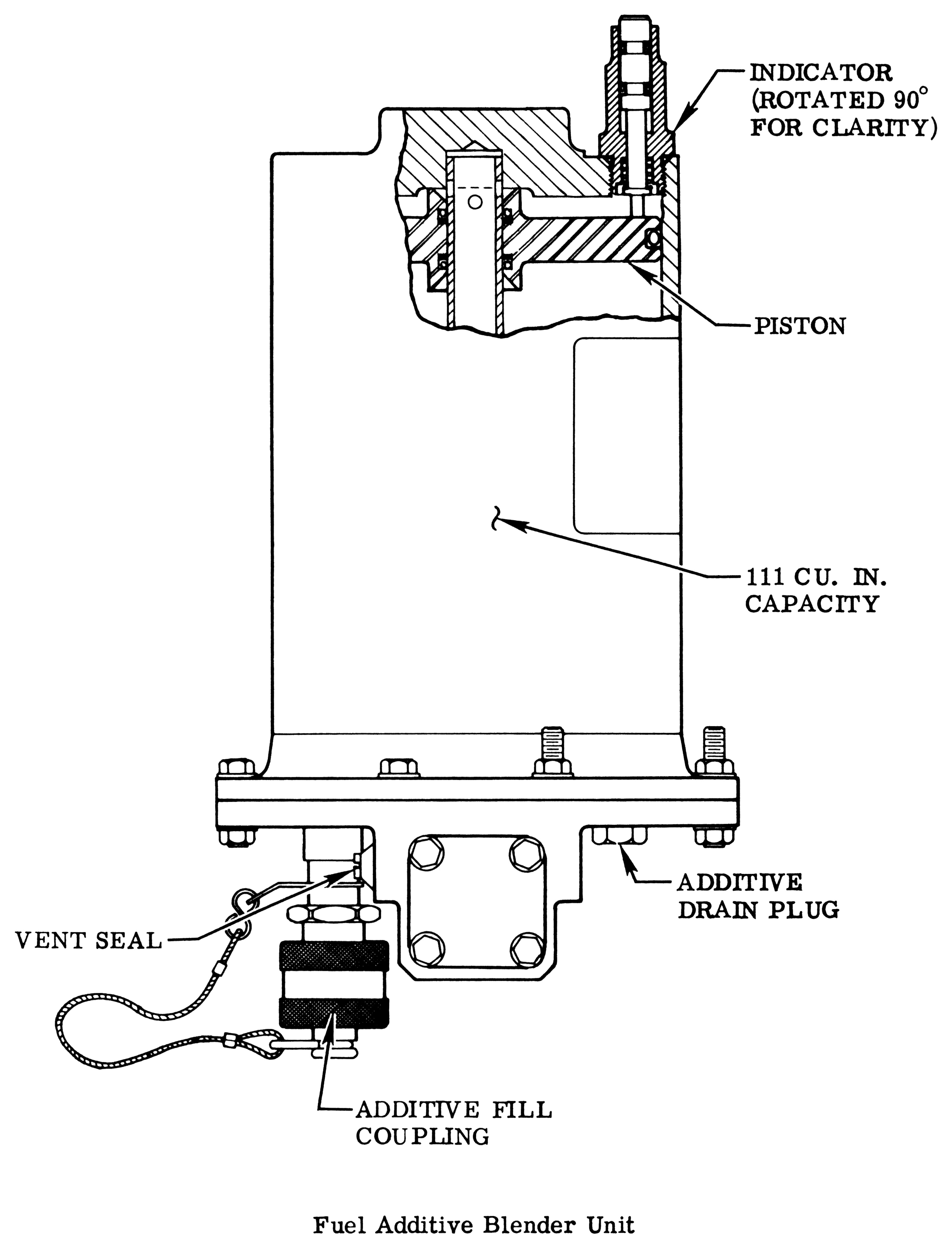
The blender unit was a small, simple cylinder, the body of which is nearly 9" tall and about 5 3/8" in diameter, which (according to various sources) held approximately 105 or 111 cubic inches (about 58 or 61 ½ fluid ounces, or a bit under a half gallon) of the additive.
From page 4-15 of the Saturn IB Flight Manual (MSFC-MAN-205, April 15,
1968). Located in the Mauldin Collection, Dept. of Archives/Special
Collections, M. Louis Salmon Library, University of Alabama in
Huntsville.
Scan and cleanup by heroicrelics.
It was mounted on the engine's combustion chamber, near the LOX turbopump:
Click image for a 2283x2716 pixel version of this image in a new window.
Adapted from page 4-10 of the Saturn IB Flight Manual (MSFC-MAN-205,
April 15, 1968). Located in the Mauldin Collection, Dept. of Archives/Special
Collections, M. Louis Salmon Library, University of Alabama in
Huntsville.
Scan, cleanup, and adaptation by heroicrelics.
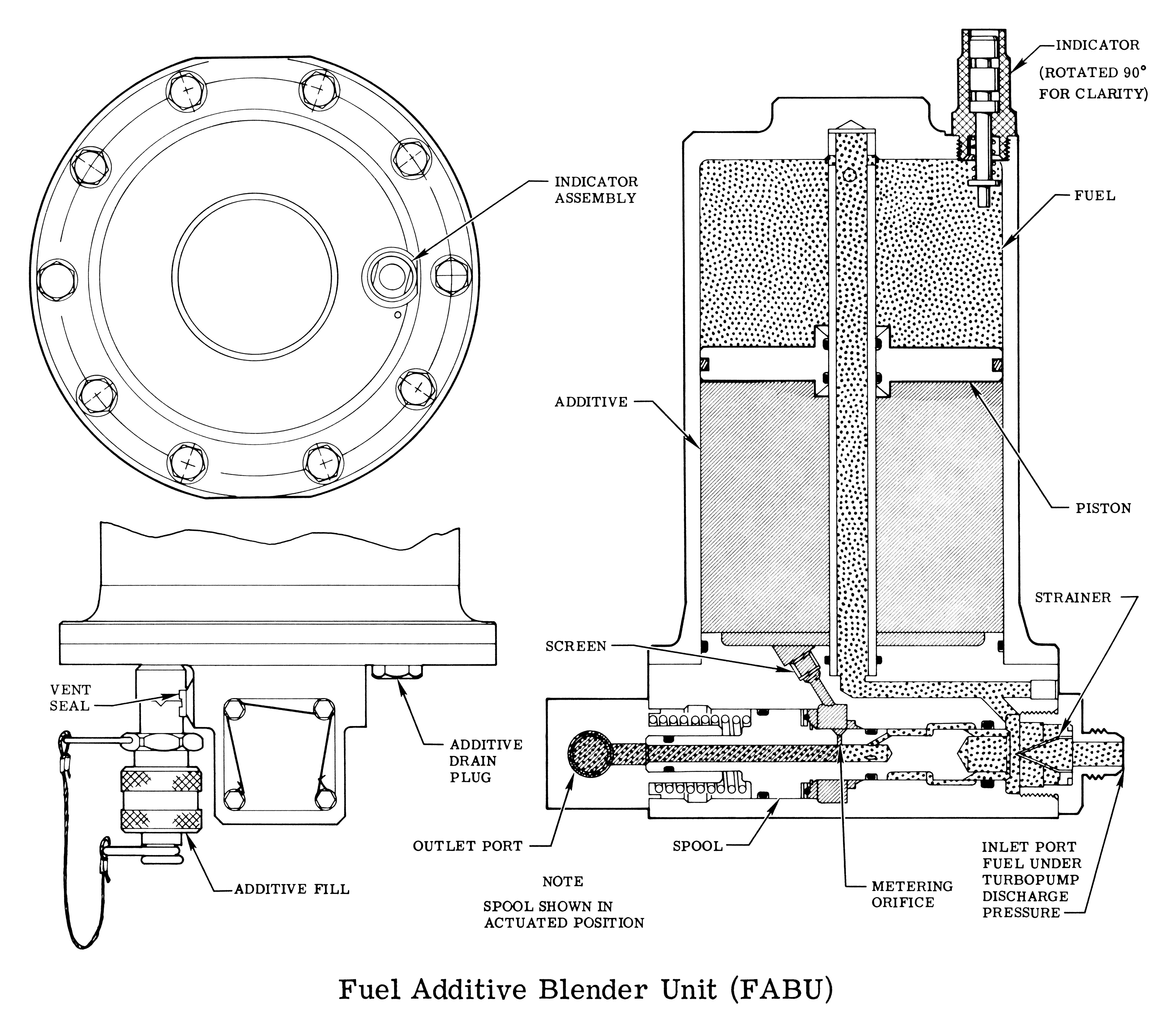
Lubricant flow began during the engine startup sequence, when control-pressure fuel from the turbopump increased to 70 to 150 psig. At that point, fuel pressure opened the FABU shuttle check valve (FABU spool). A portion of the fuel was directed to the FABU piston, pressurizing the Oronite. As the fuel pump discharge pressure increased, the FABU spool opened farther until the metering orifice allowed the Oronite (2.75±0.75 percent by volume) to blend with the fuel. The mixture left the FABU and was routed to the turbopump gearcase via a 3/8" diameter discharge line with a nominal flowrate of 0.63 lb/sec, for a lubricant consumption rate of 5 to 6 gpm.
Click image for a 4156x3630 pixel version of this image in a new window.
From page 1-55 of the H-1 Rocket Engine Models H-1C and H-1D Technical
Manual: Engine Data. Located in the Saturn V Collection, Dept. of Archives/Special
Collections, M. Louis Salmon Library, University of Alabama in Huntsville,
which also makes this document available as a 14.4
megabyte PDF.
Scan and cleanup by heroicrelics.
While the lubricant was delivered to the turbopump gearbox under fuel pressure, the gearbox itself was pressurized with GN2 to prevent the lubricant from foaming at high altitudes. After injection into the turbopump gearbox, spent lubricant was drained overboard through the lube-drain relief valve, down drain lines extending down the engine thrust chamber exterior, and dumped into the engine exhaust stream.
The additive contained in the FABU was variously called Oronite, Oronite 262, RB0140-006 (Rocketdyne), or ST0140RB0013. Composed of phosphorus, zinc, and sulfur in a neutral-base oil diluent, it was loaded into the FABU when the engine was being serviced prior to firing. A plunger-type indicator on top of the FABU extended when the unit is full. There appear to have been several design iterations of the FABU, as some diagrams and units I've photographed have the plunger on the center raised portion of the FABU while others have it closer to the edge of the unit. The number of bleeder plugs on the top appears to have changed, from one to two to (apparently on some units) none at all.
Click image for a 3254x4265 pixel version of this image in a new window.
From page 79 of H-1 Rocket Engine Technical Data (R-3620-1A),
located in a private collection.
Scan and cleanup by heroicrelics.
It was important to maintain additive viscosity to ensure proper turbopump lubrication. The additive was maintained at a temperature of 120+/-10° F via an integral, thermostatically-controlled, resistance-type heater. The 300W heater received power through a 115-V, 60-Hz, 3-phase, 4-wire system from a ground supply. The heaters on the engines were turned on prior to loading the stage's liquid oxygen (approximately 8 hours before liftoff) and were turned off when the ground control computer determined that all engines were running, just before umbilical disconnect.
Additive temperature was one of the H-1 engine's critical "redline" parameters which, if exceeded, would produce unsafe or unsatisfactory operations. If the lube additive temperature fell out of the 105° F to 160° F range, the additive consistency would cause improper mixture of fuel and additive, resulting in improper turbopump lubrication.
Several H-1 engines on display today still retain their FABU heater assemblies, including the one at Neil Armstrong Air & Space, the one formerly displayed at Stennis Space Center, and the one at the Udvar-Hazy Center.
The FABU on the H-1 engine at Neil Armstrong Air & Space has a heater assembly in pristine condition:

Click image for more information about this picture; opens in a new window.
From my H-1 engine picture set
at Neil Armstrong Air & Space.
Picture by heroicrelics.org.
The heater assembly on the FABU on the H-1 engine turbopump previously installed in Marshall Space Flight Center's Cold Calibration Test Stand, exposed to the elements for some 50 years, has faded to an almost-pink color. Additionally, its wire laces have been removed, exposting the FABU within:

Click image for more information about this picture; opens in a new window.
From my H-1
Engine Turbopump from Cold Calibration picture set at the Marshall Space Flight Center.
Picture by heroicrelics.org.
And one final diagram showing the FABU itself, its mounting bracket on the H-1's combustion chamber, its associated plumbing, and its heater assembly:
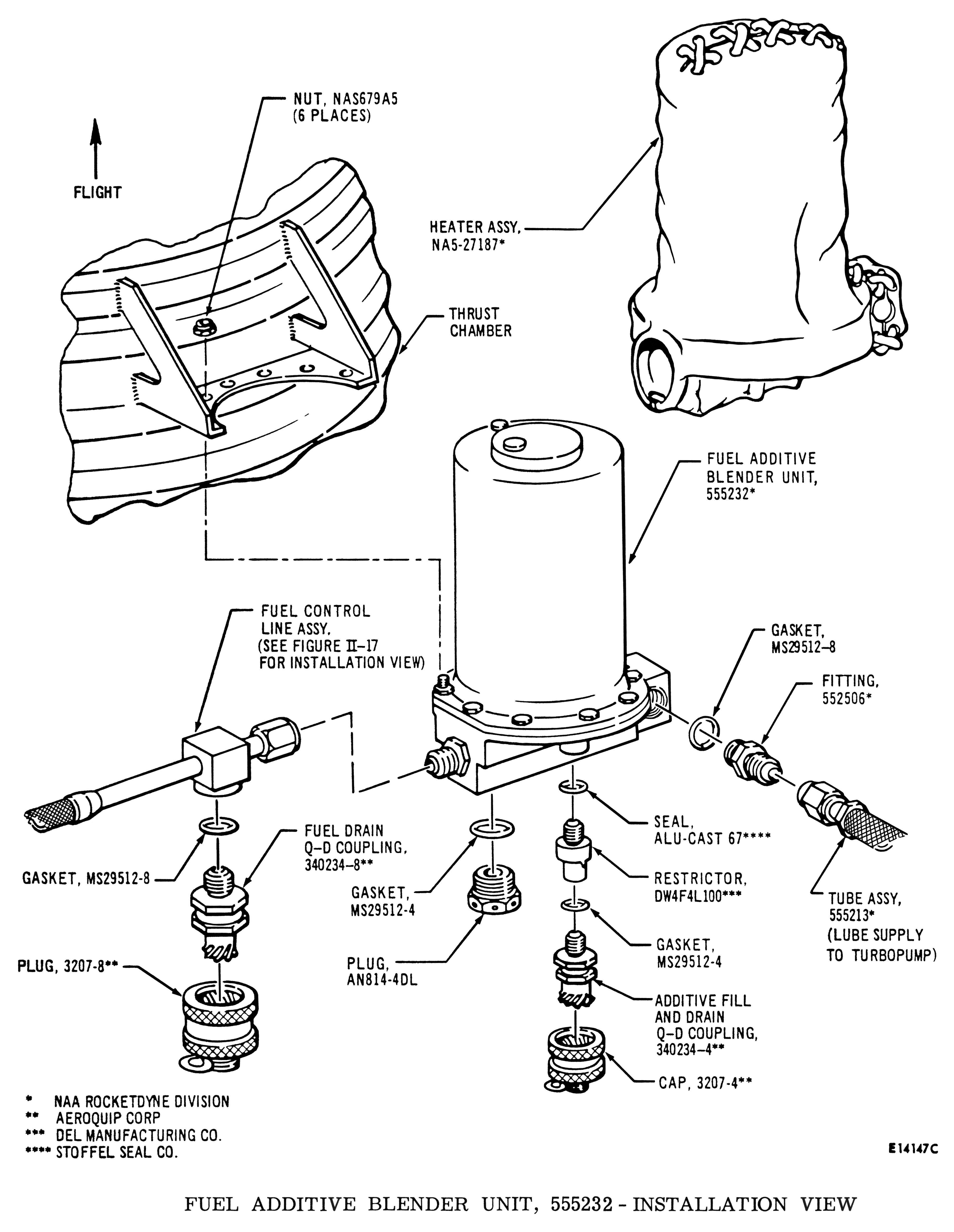
Click image for a 4007x5175 pixel version of this image in a new window.
From the II-38 of the Saturn IB, Volume II: S-IB Stage, located in
the Saturn V Collection of the Dept. of Archives/Special
Collections, M. Louis Salmon Library, University of Alabama in
Huntsville, which also makes it available as a 6.4
megabyte PDF.
Scan and restoration by heroicrelics.
Whenever the H-1 engine was stored or transported, it was clad in a variety of covers and closures to protect vulnerable components and surfaces (e.g., see my H-1C and H-1D photos). As detailed in the diagram below, the FABU warranted its own set of covers.
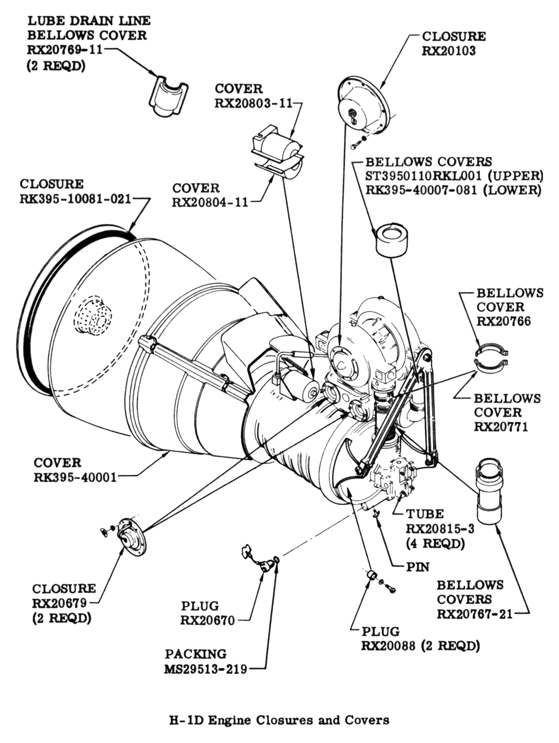
Click image for a 1782x2368 pixel version of this image in a new window.
From page 34 of the H-1 Rocket Engine Technical Manual: Pocket Data
Supplement, Models H-1C and H-1D (R-3620-1A). From the personal
collection of Alan Lawrie.
Scan by Alan Lawrie. Cleanup by heroicrelics.
The bulk of the descriptive text was taken, sometimes nearly verbatim, from the Skylab Saturn IB Flight Manual, H-1 Rocket Engine Models H-1C and H-1D Technical Data, and the Saturn IB News Reference.
Thanks to Mark Trotter (http://www.trottermatic.com) for FABU measurements.