
Jupiter Tail Unit
This page serves as a repository for diagrams of the Jupiter tail section and its S-3D engine.
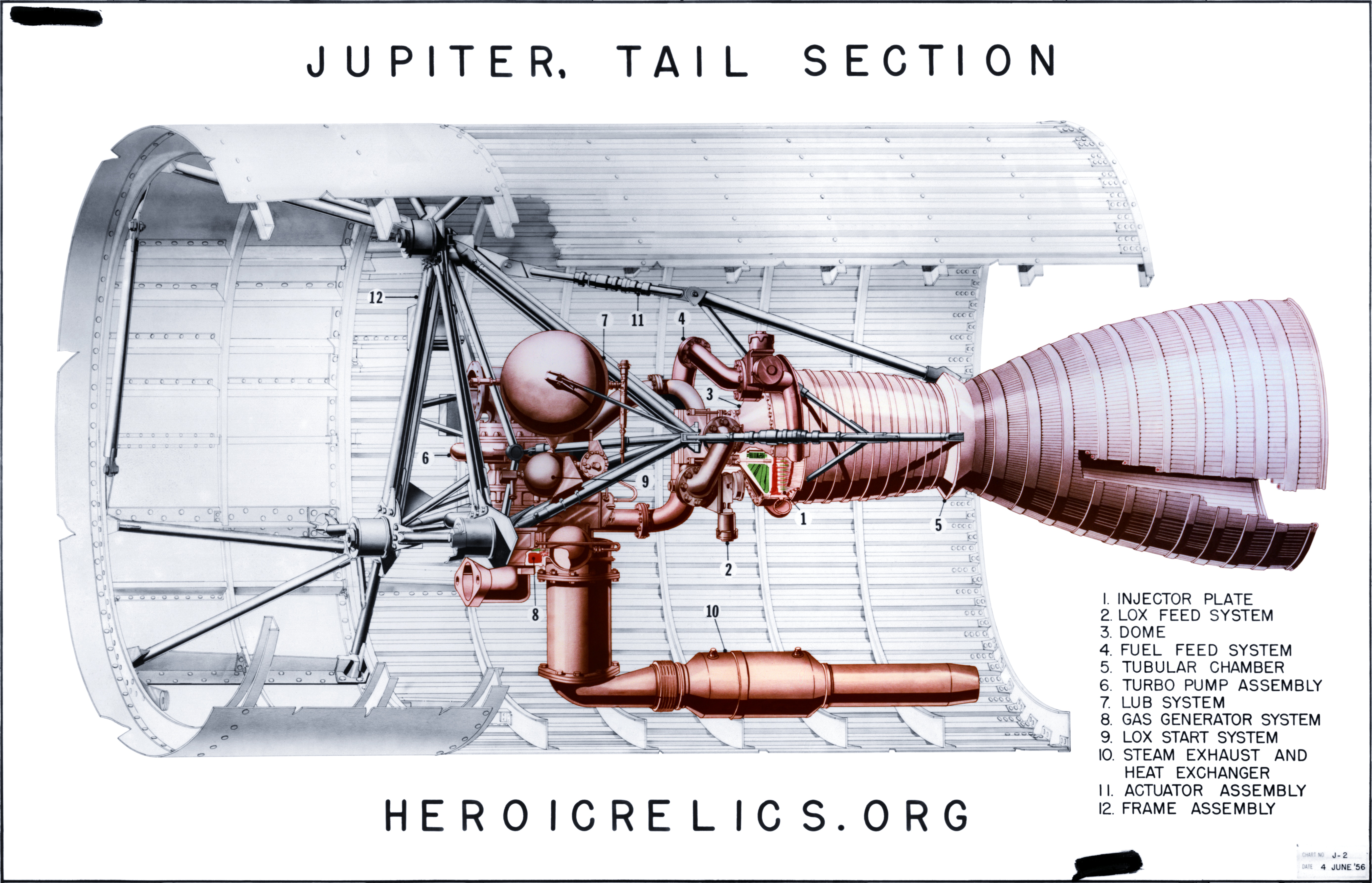
This diagram of the Jupiter tail section has call-outs for the major components and subsystems. The diagram is labelled "Chart No. J-2" with a date of "4 June '56".
The original of this particular diagram was badly yellowed and faded, so these colors may differ from the colors of the original diagram.
Click image for a 5549x3571 pixel version of this image in a new window.
From the private collection of Dave Christensen
Scan and reconstruction by heroicrelics.
The call-outs for the diagram are
- Injector Plate
- LOX Feed System
- Dome
- Fuel Feed System
- Tubular Chamber
- Turbo Pump Assembly
I've got a number of similar, yet slightly different, diagrams of the Jupiter missile tail.
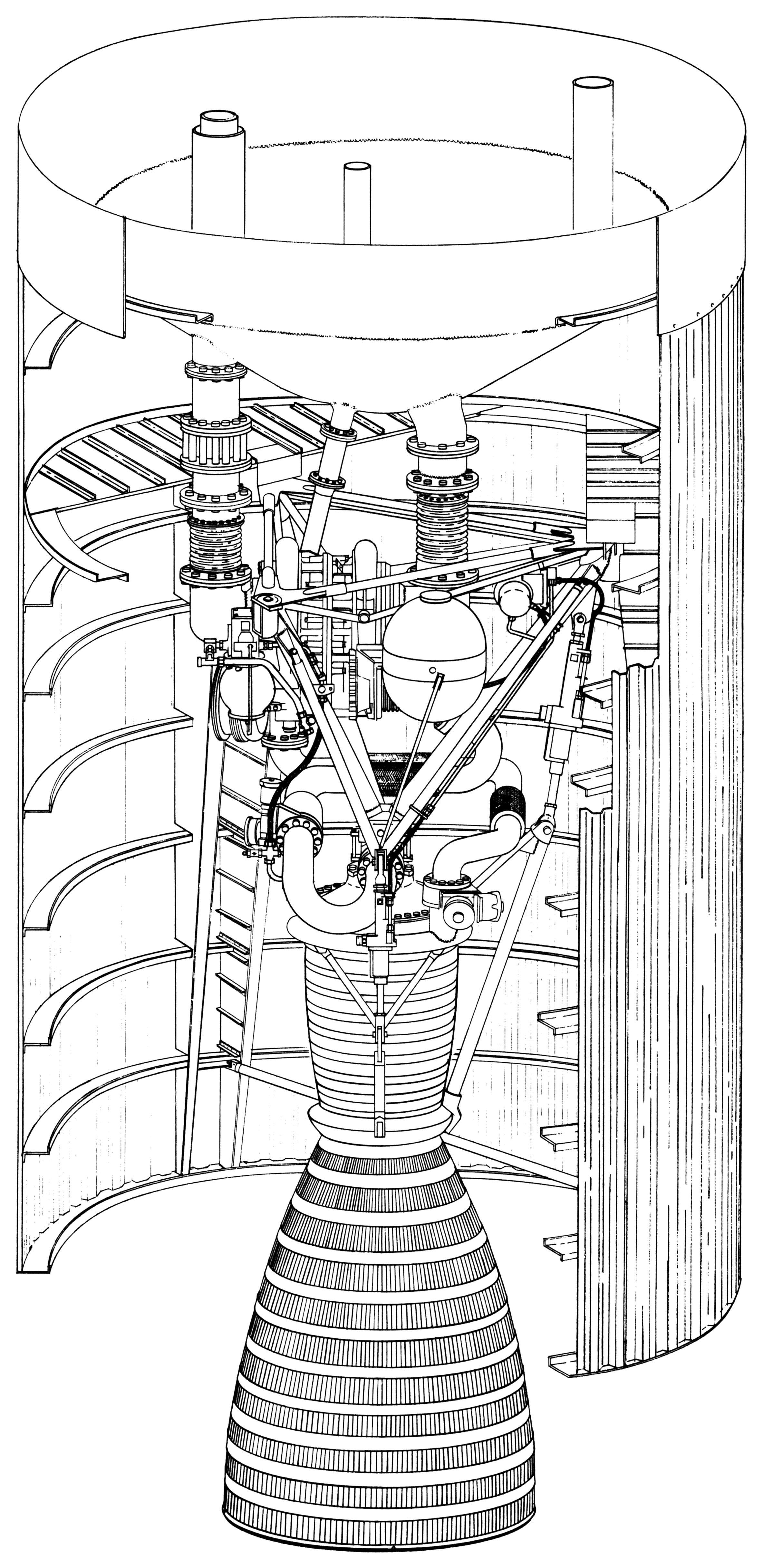
This diagram shows the aft end of the LOX tank and the LOX and fuel feed lines leading to the S-3D engine. Items not depicted in this diagram include the turbine exhaust duct and heat exchanger.
Click image for a 2368x4869 pixel version of this image in a new window.
From the private collection of Dave Christensen
Scan and clean-up by heroicrelics.
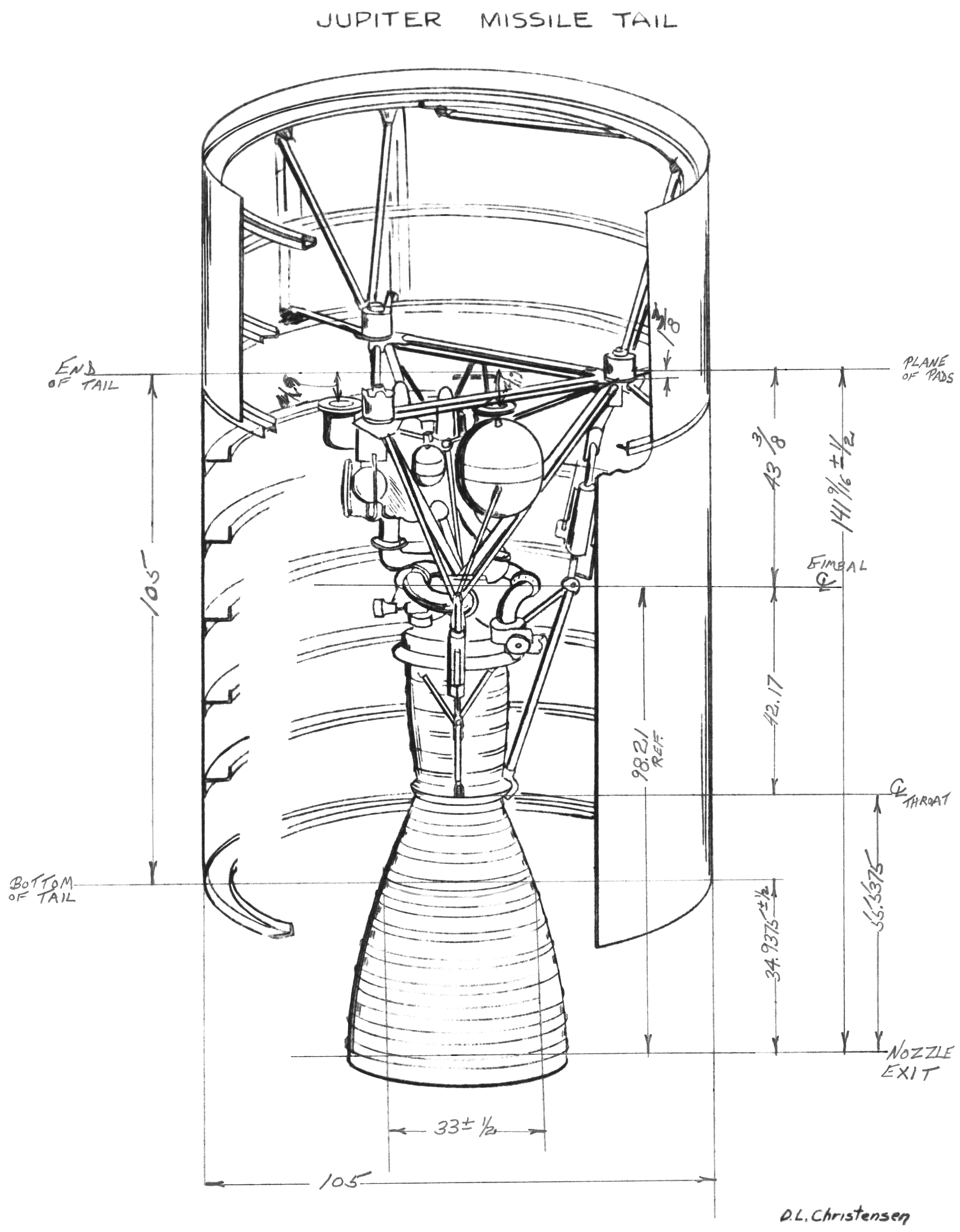
This diagram contains a number of dimensions concerning the Jupiter's tail unit. The diagram excludes the propellant tank and feed lines, but shows the pads on the forward end of the engine's thrust frame (where thrust from the engine is transmitted to the missile's airframe).
Also missing (oddly so) is the turbine exhaust duct and heat exchanger; it appears to have literally been erased from the diagram (lower left).
We see in this diagram that the aft skirt is 105 inches tall (the same as the diameter of the missile), that the engine extends 34 15/16" past the bottom of the tail, and that centerline of the S-3D's throat is 55.5375" from the nozzle exit, and that the S-3D is 98.21" tall, from the gimbal plane to the nozzle exit.
Click image for a 4860x6235 pixel version of this image in a new window.
From the private collection of Dave Christensen
Scan and clean-up by heroicrelics.
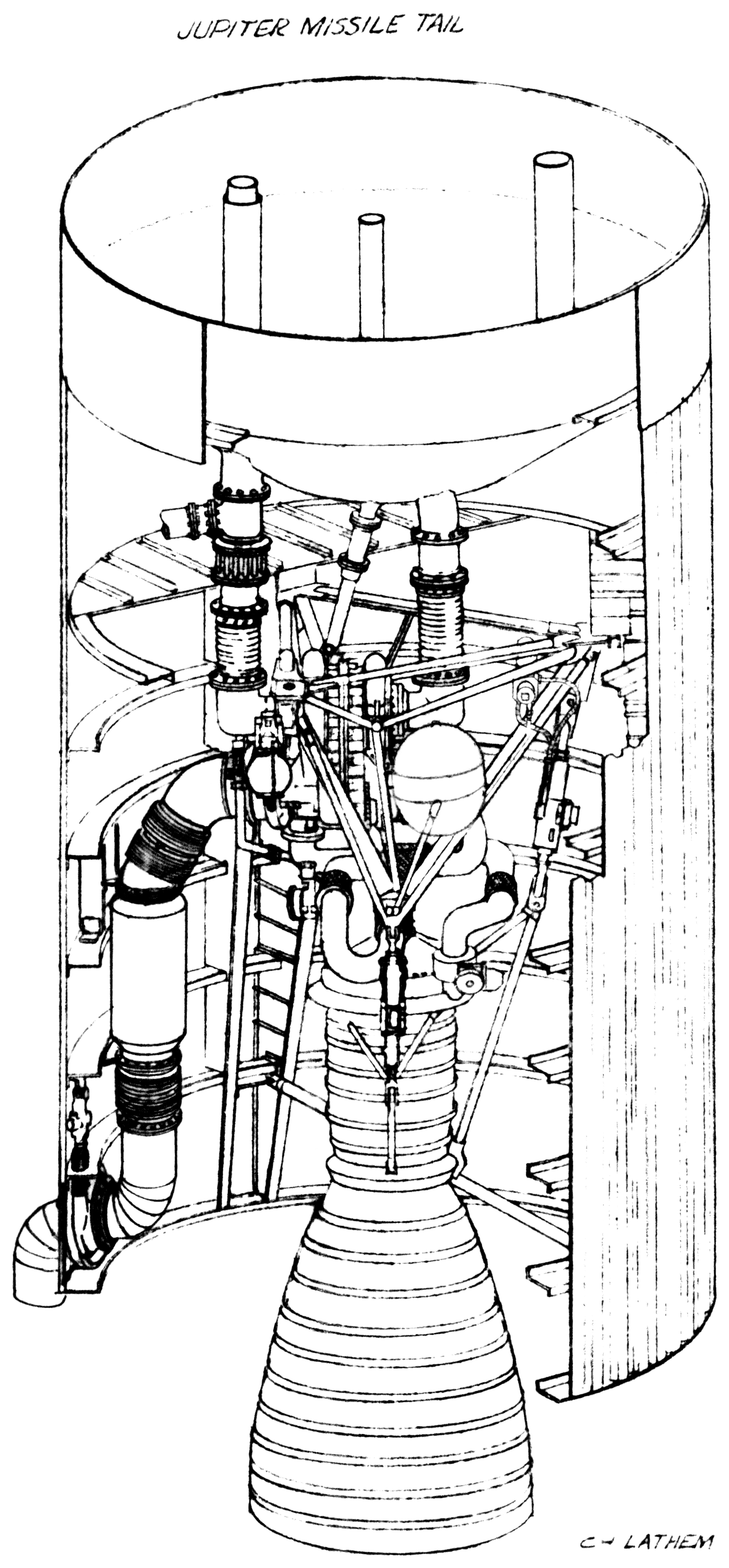
This diagram again shows the aft of the LOX tank and the propellant feed lines, as well as the elusive turbine exhaust duct and heat exchanger.
This particular diagram's original was in substantially poorer shape than the two above, and so this diagram is a bit rough-looking.
Click image for a 2883x6199 pixel version of this image in a new window.
From the private collection of Dave Christensen
Scan and clean-up by heroicrelics.
Here's diagram another diagram containing Jupiter tail unit dimensions. This diagram includes the LOX tank and propellant feed lines, the pads on the forward end of the engine's thrust frame, and the turbine exhaust duct and heat exchanger.
A few dimensions differ from the diagram above, but most of the differences are a matter of a fraction of an inch.
The original of this diagram, too, was in very poor shape. At first glance, this diagram looks like the one immediately above, but there are a number of differences. (If the diagrams had been alike save for the dimensional information, I might have saved the better part of a weekend, scraping away pixels to reveal an engine.)

Click image for a 4640x6488 pixel version of this image in a new window.
From the private collection of Dave Christensen
Scan and clean-up by heroicrelics.
I have photos of the Jupiter tail unit interior at Air Power Park and the less-complete Jupiter tail unit interior at the the U.S. Space & Rocket Center.