
The S-3D vs. the H-1 Rocket Engine
When one reads about the H-1 rocket engine, it is often said that the the S-3D (Jupiter and/or Thor) engine was uprated from 150,000 lbs of thrust and "simplified" in order to produce the H-1. This page hopes to enumerate some of the ways in which the S-3D was simplified.
Reducing complexity reduces the number of parts required for an engine system; fewer, less-complex parts improves reliability (as there are few parts to fail).
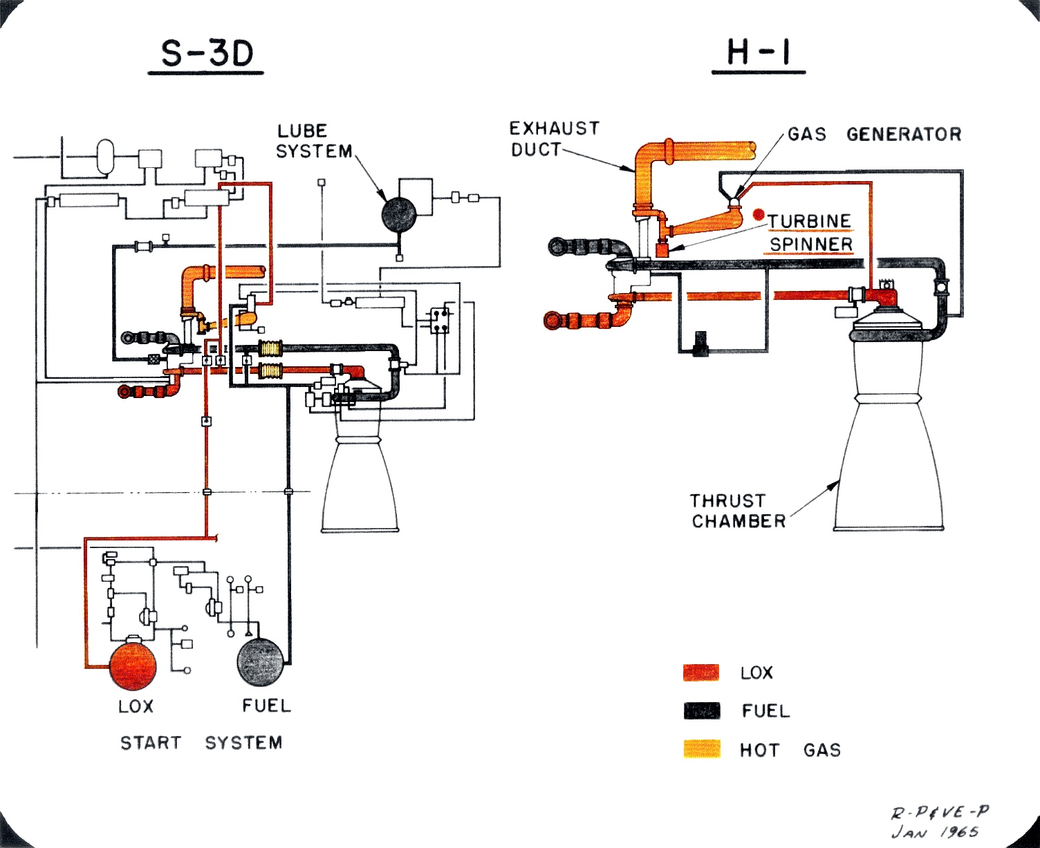
Click image for a 1504x1227 pixel version of this image in a new window.
Scan courtesy Dave
Christensen
Cleanup by heroicrelics.
Although Rocketdyne was busy making engines for the Atlas, Jupiter, and Thor missiles in the late 1950s, it also recognized the value of pure research and development. A group of engineers began experimenting with a number of concepts, including the simplification of rocket engine subsystems, in an engine program named X-1. This program experimentally introduced a number of design features which would become standard in later engines.
The X-1 replaced the electrically-controlled pneumatic system for actuating valves on previous rocket engines with valves actuated by fuel: as the turbopump came up to speed, the buildup of fuel pressure was used to open the various propellant valves. This was referred to as a "pressure ladder sequence", and ensured that valves were actuated in the proper order and only when engine conditions warranted their actuation.
Earlier rocket engines had start tank systems, containing sufficient fuel and oxidizer to power the gas generator until the turbopumps could provide propellants for continued operation (bootstrapping the turbopumps). The X-1 introduced a solid-propellant gas generator (sometimes called a "spinner") to provide the initial turbine operation.
The H-1 used solid-propellant gas generator to bootstrap the engine. The SPGG cartridge was bolted to the liquid-propellant gas generator. The engine start signal ignited the SPGG's electrical initiators, starting the solid propellant grains burning, which in turn provided 4.68 pounds of gas per second for approximately one second. This spun the turbine, driving the turbopump until fuel control pressure opened the gas generator control valve. Fuel pressure was also used to actuate the main LOX valve and fuel additive blender (see below), and to rupture the hypergol cartridge burst diaphragms (see below).
As previous large Rocketdyne engines had been hydrocarbon-based, they relied on an ignition system to initiate main combustion. These igniters were sometimes mounted on the engine's injector (e.g., the Navaho engines) or were on a rod inserted into the thrust chamber (e.g., the Redstone engine). These ignition methods were cumbersome and the debris from the igniters had the potential to damage the thrust chamber cooling tubes or (for earlier engines) the jet vanes at the engine's exit planes. The X-1 introduced the use of a hypergolic igniter which, when delivered through the injector, provided spontaneous ignition.
The H-1 inherited the use of the hypergolic igniter. A six-cubic-inch cartridge of hypergolic fluid was inserted into a housing on the side of the thrust chamber which led to a manifold feeding igniter passages on the injector. As fuel pressure increased, it burst the diaphragms on the cartridge, releasing the triethyelaluminum (TEA), a pyrophoric (i.e., ignites spontaneously in the presence of oxygen) fluid, to the combustion chamber and initiating main combustion.
Rather than using oil stored in a separate tank to lubricate the turbopump gearbox, the X-1 used RP-1, blended with a small amount of lubricant additive, for this purpose. In addition to simplifying engine design, this also eliminated a potential source of contamination.
The H-1 incorporated this lubrication scheme. It used a fuel additive blender unit (FABU) to mix RP-1 from the fuel pump discharge with an additive variously described as RB0140-006 (Rocketdyne) or Oronite. The mixture was then introduced into the turbopump gearbox to lubricate and cool the gearbox components.
The H-1 had a number of additional simplifications over the S-3D. It mounted its turbopump on the thrust chamber (rather than on the missile body, as with the S-3D). This simplified system high-pressure plumbing, minimizing pressure drop. It also allowed the propellant high-pressure ducts to be very short and rigid, replacing the longer ducts which had to provide enough flexibility to allow for engine gimaballing.
The H-1, whose thrust control requirements were less rigid than the Jupiter (which required complex thrust controls to accurately deliver its payload to the target), calibrated its thrust via simple, fixed orifices.
Here is a somewhat more detailed (although less colorful) version of the diagram above:
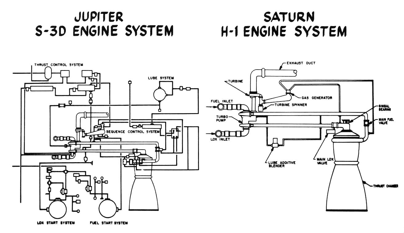
Click image for a 1314x760 pixel version of this image in a new window.
Scan courtesy the NASA
History Office
Cleanup by heroicrelics.
Just over one year into the Saturn I program, the ABMA was already making suggestions to further simplify the H-1. In my "Saturn H-1 Engine Design Features" memo, there's a discussion about incorporating simplification features from what's referred to as "Engine 'X'", including elimination of the hypergolic ignition system, using the SPGG to ignite the main propellants; removing the FABU, simply using RP-1 to lubricate and cool the gearbox; and replacing the liquid propellant gas generator with an engine tap-off cycle (in which hot gases from the combustion chamber are tapped off to power the turbine). None of these simplifications ever made it into the H-1.
Information on this page was taken from Rocketdyne: Powering Humans into Space, H-1 Rocket Engine Models H-1C and H-1D Technical Manual: Engine Data (located in the Saturn V Collection, Dept. of Archives/Special Collections, M. Louis Salmon Library, University of Alabama in Huntsville, which at one time made this document available as a 14.4 megabyte PDF, and Stages to Saturn.