Redstone Missile Overview
This page serves as a repository for overall Redstone missile photos and diagrams.
The Redstone missile (strictly speaking, the "Redstone Field Artillery Missile System") was the United States' first large ballistic missile system, developed by the Army, under the guidance of the von Braun German rocket team. At the time of its development, it was considered a medium-range missile (with a range of approximately 175 nautical miles -- 200 statute miles), although by later standards it is considered a short-range missile. The missile's name, "Redstone", was taken from the Redstone Arsenal, the facility to which the rocket team moved in 1950.
The Redstone was intended to launch tactical battlefield nuclear weapons to provide support for the field army and supplement the range of firepower of existing artillery. Although never used to launch nukes in a battle, the Redstone was the first U.S. missile to launch live nuclear warheads, during the Teak and Orange tests of Operation Hardtack. Both of these were high-altitude airbursts, during which the high-altitude electromagnetic pulse (EMP) effect was discovered.
Fifty missiles were flight-tested in the Redstone R&D program, although many of these missile firings served multiple purposes. Twenty-five missiles were designated as "Jupiter A" missiles, as they were used to obtain design data, to prove the guidance system, evolve separation procedures, and develop other special information that was used in the Jupiter program.
Perhaps the most famous of these were the modified Redstones. Three were designated as "Jupiter-C" missiles, used in the Jupiter reentry vehicle test program. Six were designated as "Juno I" and were used to launch satellites, including the first U.S. satellite, Explorer I. Two were used in Operation Hardtack, as described above.
And, of course, the Redstone was modified, man-rated, and used to launch the early Project Mercury missions.
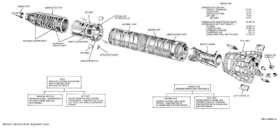
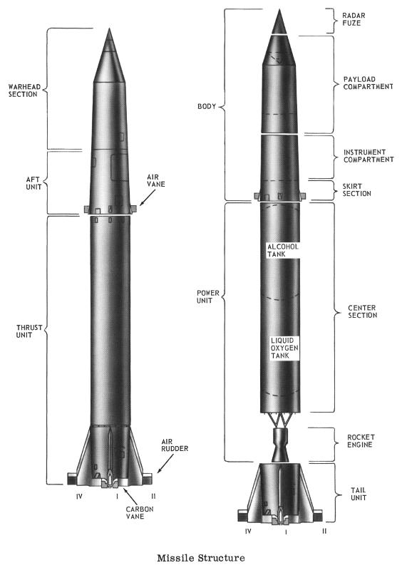
Structurally, the Redstone missile was composed of several sections, compartments, and units; many of these were subdivided and combined into a confusing array of terms.
Click image for a 1920x876 pixel version of this image in a new window or
click here for a 10546x4814
pixel version of this image in a new window.
From p. II-2 of This is Redstone, located in the Dunaway
collection , Dept. of
Archives/Special Collections, M. Louis Salmon Library, University of
Alabama in Huntsville. Available in electronic format from My Army
Redstone Missile Days
Scan, reconstruction, and cleanup by heroicrelics.
Callouts in this diagram include
- Radar fuze
- Warhead section
- Payload compartment
- Instrument compartment
- Aft unit
- Instrument compartment
- Skirt compartment
- Air vanes
- Counterforts (4)
- Explosive screws
- Spatial air jet nozzles (4)
- Center unit
- Alcohol tank
- Liquid oxygen tank
- Rocket Engine
- Tail unit
- Air rudders (4)
- Carbon jet vanes (4)
The tail unit was the shroud surrounding the engine. It contained the missile's fins and jet vanes, and the entire missile rested on its launcher table on the tail unit.
The center section contained the fuel (alcohol) and liquid oxygen tanks. Unlike the V-2, which employed separate propellant tanks placed inside of the missile's airframe, the Redstone used tanks integral to the airframe and the propellant tanks utilized a dividing bulkhead.
The center section and the rocket engine were together called the power unit, and the combination of the power and tail units was called the thrust unit
After powered flight, the thrust unit was expended and jettisoned via explosive screws, leaving the missile's body to continue to the target. This is another improvement over the V-2: The V-2's warhead remained attached to the entire missile body, and the V-2 suffered from aerodynamic breakup as the entire missile reentered the atmosphere. On the Redstone, the thrust unit can be made of a relatively light material (primarily aluminum); only the body needed to be constructed of material (primarily alloy steel) which could withstand the rigors of reentry.
The missile's body was composed of the aft unit and warhead section; each of these sections were further subdivided.
Having jettisoned the thrust unit (with its air rudders and jet vanes), the aft unit took over the task of guiding the warhead to its target. The skirt section at the aft of the aft unit contained another set of air vanes as well as "spatial air jet nozzles" to adjust the flight of the warhead. Forward of the skirt section is the instrument compartment, which contained the guidance and control equipment.
Forward of aft unit was the warhead section, which remained attached to the aft unit throughout the flight. The warhead section was divided up into the payload compartment ("payload" euphemistically referring to the nuclear warhead) at the rear and the radar fuze at the tip.
Click image for a 845x1200 pixel version of this image in a new window or
click here for a 3562x5056
pixel version of this image in a new window.
From p. II-0 of This is Redstone, located in the Dunaway
collection , Dept. of
Archives/Special Collections, M. Louis Salmon Library, University of
Alabama in Huntsville. Available in electronic format from My Army
Redstone Missile Days
Scan and cleanup by heroicrelics.
The Redstone was 69 feet 4 inches tall and had a diameter of 5'10" and could deliver a 6,305 pound payload 175 nautical miles (201 statute miles) in 375 seconds; powered flight lasted about 119.5 seconds.
The 5'10" tank diameter converts to 70 inches, and Saturn aficionados will recognize this as the diameter of the outer propellant tanks on the Saturn I and IB. When the von Braun team was finally authorized to make a large space booster, they reduced development time by using the existing tooling and procedures from the Redstone and Jupiter tanks to cluster together tankage for this new rocket.
Click image for a 1714x3519 pixel version of this image in a new window
From p. II-1 of This is Redstone, located in the Dunaway
collection , Dept. of
Archives/Special Collections, M. Louis Salmon Library, University of
Alabama in Huntsville. Available in electronic format from My Army
Redstone Missile Days
Scan and cleanup by heroicrelics.
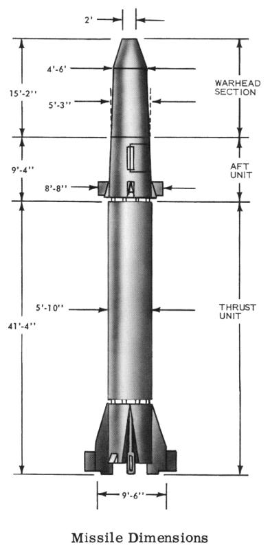
This diagram provides dimensions of various parts of the missile:
-
Warhead section
- Length, excluding fuze: 15'-2"
- Diameter of base of fuze: 2'
- Diameter of warhead section prior to nose cone: 4'-6"
- Diameter of base of warhead section: 5'-3"
-
Aft unit
- Length: 9'-4"
- Diameter including air rudders: 8'-8"
-
Thrust unit
- Length: 41'-4"
- Diameter of center unit (propellant tanks) 5'-10"
- Diameter of fins, excluding air rudders: 9'-6"
Click image for a 389x1200 pixel version of this image in a new window or
click here for a 1727x5325
pixel version of this image in a new window.
From the tile page of This is Redstone, located
in the Dunaway collection, Dept. of Archives/Special
Collections, M. Louis Salmon Library, University of Alabama in
Huntsville. Available in electronic format from My Army
Redstone Missile Days
Scan and clean-up by heroicrelics.
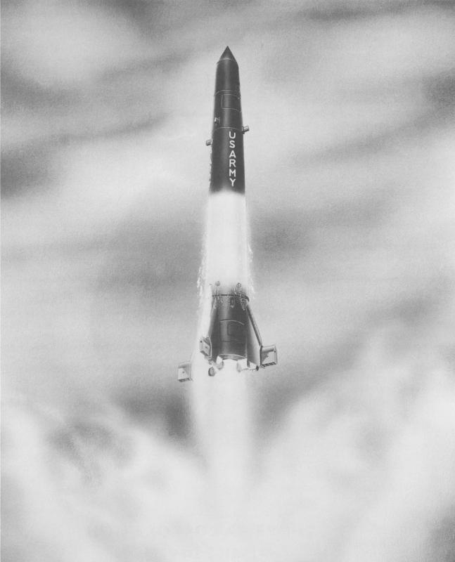
These two last diagrams are simply gratuitous drawings of Redstone launches. First, a simple line drawing. Note the LOX cloud emanating from the vent valve.
And a more dramatic drawing, showing the aft end illuminated by the engine's exhaust. This diagram emphasizes that the LOX tank is located aft of the alcohol tank.
Click image for a 920x1200 pixel version of this image in a new window or
click here for a 3875x5053
pixel version of this image in a new window.
From the frontispiece of This is Redstone, located
in the Dunaway collection , Dept.
of Archives/Special Collections, M. Louis Salmon Library, University of
Alabama in Huntsville. Available in electronic format from My Army
Redstone Missile Days
Scan and restoration by heroicrelics.


