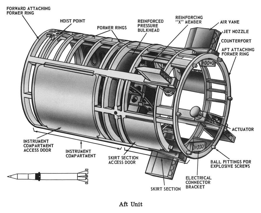
Redstone Missile Aft Unit
The most confusingly-named section of a Redstone missile is the aft unit: It is not the aft-most section of the missile; that is the tail unit. Rather, the aft unit is located forward of the center unit and aft of the warhead section. I assume that it is is called the aft unit because it is the aft-most part of the portion which remains after the thrust unit (consisting of the center unit [containing the propellant tanks], engine, and tail unit) is jettisonned. The aft unit contains the guidance system and a series of air vanes and jet nozzles used to steer the warhead to its intended target.
Click image for a 3896x3177 pixel version of this image in a new window.
Adapted from p. II-5 of This is Redstone, located in the Dunaway
collection, Dept. of
Archives/Special Collections, M. Louis Salmon Library, University of
Alabama in Huntsville. Available in electronic format from My Army
Redstone Missile Days
Scan, cleanup, and adaptation by heroicrelics.
Callouts in this diagram include
- Forward attaching former ring
- Hoist point
- Former rings
- Reinforced pressure bulkhead
- Reinforcing "X" member
- Air vane
- Jet nozzle
- Counterfort
- Aft attaching former ring
The aft unit was 9 feet 4 inches tall. It had a diameter of 5 feet 10 inches where it met the center unit and tapered to 5 feet 3 inches where it met the warhead section.
The aft former ring of the aft unit had six ball fittings which mated to corresponding sockets on the center unit, held together with explosive screws. After the propellant tanks were empty, the explosive screws fired to separate the aft unit from the thrust unit and two expulsion cylinders on the forward end of the center unit provided positive separation. The aft unit was permanently attached to the warhead section with four similar ball and socket fittings, but without the explosive screws.
As the aft unit stayed with the warhead during re-entry, it required a heavier construction than the center unit and was formed of an alloy steel skin riveted to a framework of aluminum ring frames and stringers.
A reinforced pressure bulkhead divided the aft unit into two sections, the instrument compartment and the skirt section. The instrument compartment, forward of the pressure bulkhead, contained the guidance and control compartment and housed the inertial guidance system's ST-80 stabilized platform. The skirt section, aft of the pressure bulkhead, was open-ended and housed two high-pressure air spheres which supplied the aft unit's pneumatic systems. Four actuators which turned the air vanes were located in the aft end of the skirt section.
Two large doors, fitted with silicone rubber gaskets assure an airtight seal, provided access to the instrument compartment. An access door in the skirt section provided access to equipment when the aft unit was mated with the thrust unit.
The two high-pressure spheres in the skirt section were ground-serviced via a high-pressure fill line from the thrust unit. The air bearing supply sphere held one cubic foot and the jet nozzle supply sphere held 1.5 cubic feet, both at 3,000 psi.
Jet nozzles, located on the air vane counterforts, provided for spatial attitude control when the air vanes exceeded an angle of ±5 degrees. Air pressure was reduced from 3,000 psi at the supply sphere to 300 psi by a pressure regulator, after which the air passed to a manifold and on to the jet nozzle solenoid valves.
The second sphere supplied an air supply and temperature control system for the ST-80 stabilized platform in the instrument compartment. When the stabilized platform was in operation, the pendulums, accelerometers, and stabilizing gyros were supplied with dried air at a flow rate of 11 scfm at a pressure of 32.5 psi.
Much of the descriptive text on this page was taken from This is Redstone.

