
F-1 Rocket Engine Gimbal Bearing
The F-1 rocket engine thrust chamber assembly consisted of a two-piece thrust chamber, an injector, an oxidizer dome and manifold, and a gimbal assembly. The gimbal bearing attached to the oxidizer dome via eight bolts.
Exploded view of the F-1 thrust chamber assembly, including the gimbal bearing
and associated bolts, LOX dome, and injector.
Click image for a 1332x1135 pixel version of this image in a new window.
From page 1-7 of the F-1 Engine Familiarization Training Manual,
located in the archives of the U.S.
Space & Rocket Center. A superset of this document is also available
from archive.org.
Extraction and cleanup by heroicrelics.org.
The gimbal bearing was used to attach the thrust chamber to the vehicle structure or test stand. It weighed 425 pounds or 426 pounds, depending upon the source to which one refers.
Diagram of the F-1 rocket engine gimbal bearing assembly.
Click image for a 3778x4745 pixel version of this image in a new window.
From page 15 of Saturn V Booster - The F-1 Engine by D.E. Aldrich.
Located in the Saturn V Collection, Dept. of Archives/Special
Collections, M. Louis Salmon Library, University of Alabama in
Huntsville.
Scan and clean-up by heroicrelics.
The gimbal assembly was a spherical, low-friction, steel universal joint, incorporating ball and socket-type bearing surfaces. A composition of Teflon-impregnated Fiberglass (Fabroid) was bonded to the bearing surfaces of the sockets. The seat contained the Fabroid-lined socket section within which the ball sections of the body moved and incorporated two arms that supported the shaft. The body incorporated the ball section for the seat socket and the Fabroid-lined socket section for the ball section of the block. The block contained the ball section for the Fabroid-lined socket section of the body. The sides of the block were lined with Fabroid as were the surfaces of the hole into which the shaft fit. The shaft, through the support arms of the seat, transmitted all bearing loads between the engine and vehicle. The shaft was prevented from rotating and moving axially by two plug and screw retainers. The Fabroid liners of the gimbal assembly were lubricated at assembly and required no further lubrication.
Cut-away diagram of an F-1 rocket engine gimbal bearing, along with its gimbal
boot.
Click image for a 5732x4533 pixel version of this image in a new window.
From an unnumbered page of the F-1 Engine Training Aids, located
in the archives
of the U.S. Space & Rocket Center.
Scan and cleanup adaptation by heroicrelics.
A silicone-impregnated Fiberglass boot was installed around the gimbal bearing to protect the assembly from adverse environmental conditions. The gimbal boot was removed for certain maintenance procedures and while mating the engine to the S-IC stage, but was reinstalled on a loose engine for shipping, handling, and storage and was also reinstalled after the engine was mounted on the stage.
In addition to the seat, body, block, and shaft discussed above, the gimbal assembly also included a misalignment plate (sometimes spelled as a "misalinement" plate in vintage Rocketdyne documentation). This plate was the interface between the oxidizer dome and gimbal assembly and incorporated guides and threaded-type adjustment devices to laterally position the assembly. Eight slotted holes in the plate flange, which coincide with eight threaded inserts in the dome flange, allowed lateral adjustment of the plate along the x-axis. Eight oversized holes in the seat flange, coinciding with the slotted holes in the plate, allowed lateral adjustment of the seat along the z-axis. The bottom guide recessed into a guide slot machined into the dome. The seat rested on the misalignment plate and had a guide slot into which the upper guide of the misalignment plate recessed.
The gimbal bearing underwent an alignment procedure any time it was installed or reinstalled or whenever maintenance tasks might have disturbed the delivered aligned position of the gimbal". This alignment procedure was known as "paralleling gimbal bearing to thrust chamber injector".
Saturn V first stage thrust vector changes were achieved by gimballing the entire engine. The gimbal bearing allowed the engine to be gimballed 6° any direction from center by the gimbal actuators attached to the engine by two outriggers on the thrust chamber body.
The gimbal bearing assembly permitted the engine to be rotated about its x- and z-axes, enabling the vehicle's guidance system to perform vehicle pitch, yaw, and roll commands.
Detail of an F-1 rocket engine gimbal bearing.
Click image for a 3630x2292 pixel version of this image in a new window.
Adapted from my F-1 Rocket Engine General
Configuration page.
Scan, cleanup, and adaptation by heroicrelics.
During transportation, handling, and storage it was desirable to immobilize the gimbal bearing to prevent unwanted movement. Four G4059 Gimbal Bearing Locks were used for this purpose.
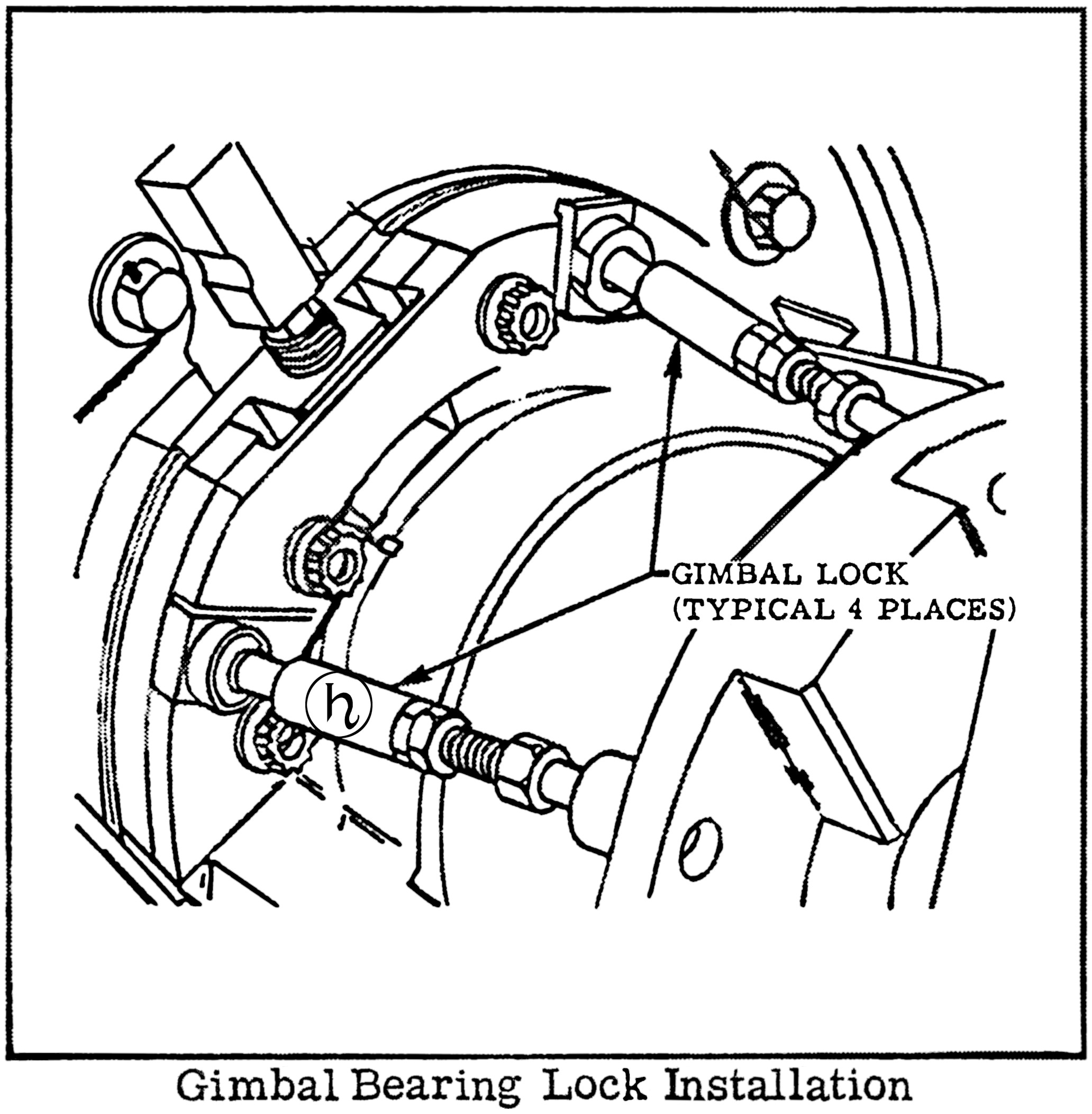
Diagram of an F-1 rocket engine gimbal bearing.
Click image for a 2064x2105 pixel version of this image in a new window.
From page 1-29 of the F-1 Rocket Engine Technical Manual: Operating
Instructions (R-3896-11), formerly available from the NASA Technical
Reports Server. A lower-quality scan is available from archive.org.
Extraction and cleanup by heroicrelics.
The gimbal bearing lock was a simple screwjack mechanism with socket-type interface mounts. Four gimbal bearing locks were positioned around the gimbal bearing. The length of the locks was adjusted as required to center and immobilize the gimbal.
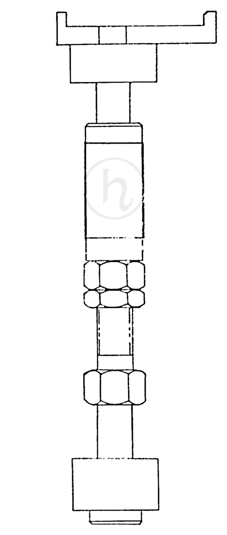
Engineering drawing of an F-1 rocket engine gimbal bearing lock.
Click image for a 745x1755 pixel version of this image in a new window.
Image courtesy Vince Wheelock.
Cleanup by heroicrelics.
The bracket at the top of the above diagram was positioned on the base of the gimbal bearing, with the tip of the lock (at bottom in the above diagram) was inserted into one of the holes on the body of the bearing used to fasten the engine to the vehicle.
The G4059 Gimbal Bearing Lock must be a relatively late development, as photos of early engines (such as the crop from a 1963 photo below) shows the gimbal bearing immobilized by the use of cables anchored to the LOX dome:
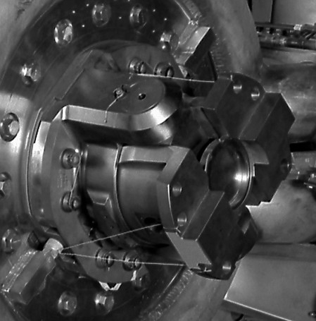
Detail of the gimbal bearing an early F-1 rocket engine, circa 1963.
Click image to open its page at the Internet
Archive in a new window.
The bulk of the descriptive text was taken, frequently verbatim or nearly so, from the F-1 Engine Familiarization Training Manual and F-1 Engine Training Aids, R-5991.