
F-1 Rocket Engine General Configuration
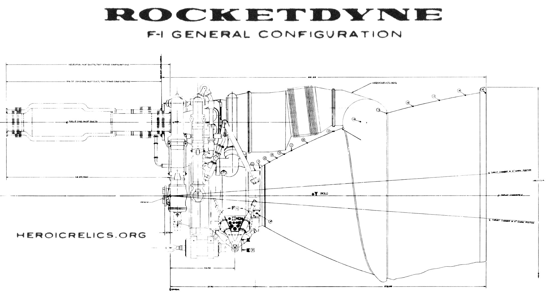
The F-1 Design Information R-2823-1 (23 August 1961), in the Dieter Huzel Collection of the archives of the U.S. Space & Rocket Center, is a very early F-1 document. As such, the F-1 engine described in this document contains a number of early design characteristics which did not survive to the production engines, including twin-elbow LOX dome inlets, externally-tied high pressure ducts, and a lack of an instrument panel (see my F-1 Major Configuration Change Points page for additional information).
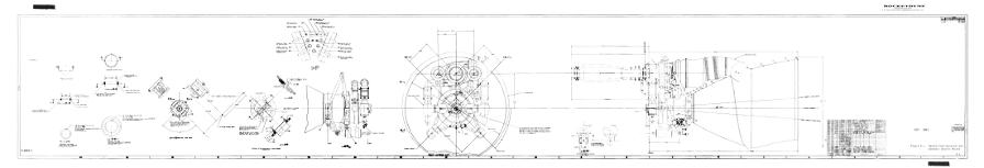
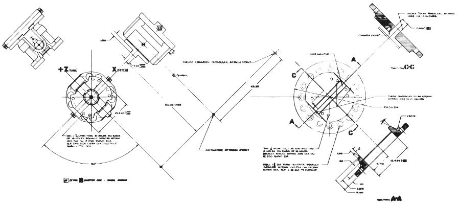
This document contains a number of diagrams of this early F-1, including a fold-out which is over 58 inches wide. This diagram includes views of the side of the thrust chamber and the forward end of the engine, with details of the propellant inlets, gimbal bearing, and engine throat. It also contains dimensional information.
Proceed to download links.
Here's a thumbnail of the diagram:
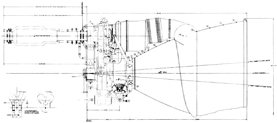
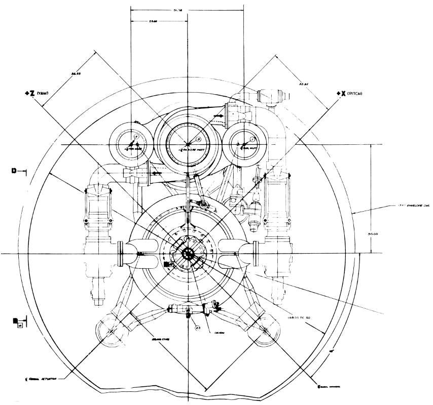
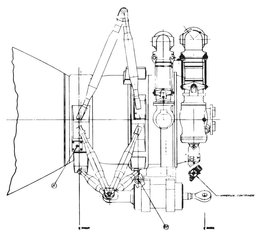
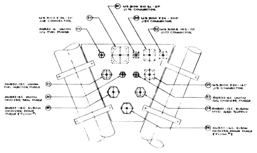
In case you can't quite make out the details of that thumbnail, here are some highlights from the fold-out:
Download Links
I've prepared several versions of this drawing:
- A 1920x1080 image depicting the side of the thrust chamber, suitable for use as your desktop wallpaper; 178k.
- A 1920x1080 image depicting the forward end of the engine, engine throat, and gimbal bearing, suitable for use as your desktop wallpaper; 252k.
- A web-resolution PDF for the casual visitor; 807K. View now.
- A 300-dpi version for serious study; 2.6 megabytes. Download now.
- A 600-dpi version for those of you who like to zoom in to 800%, or want to go to your local copy shop and print up a copy of your own, or even want to blow some drawings up to the size of your wall; 9.9 megabytes. Download now.