
F-1 Rocket Engine Gas Generator
The gas generator system provided the hot gases for driving the turbine, which in turn drove the fuel and oxidizer pumps. Turbine exhaust gases were further utilized by a heat exchanger, where additional heat was extracted to expand gases used for vehicle tank pressurization. The then-relatively cool gas generator exhaust gas was routed into the double-walled nozzle extension to provide film cooling.
Exploded-view diagram of an F-1 rocket engine gas generator, including its
combustor, injector, and ball valve.
Click image for a 2108x4429 pixel version of this image in a new window.
From page 1-26 of the F-1 Engine Familiarization Training Manual,
located in the archives of the U.S.
Space & Rocket Center. A superset of this document is also available
from archive.org.
Scan and cleanup by heroicrelics.
The gas generator started under vehicle tank head and transitioned into "boostrap" operation as the turbopump accelerated to full RPM. Oxidizer tapped off from the No. 2 LOX high-pressure duct and RP-1 from the No. 2 fuel high-pressure duct were fed to the gas generator, where they entered through the ball valve and injector and were ignited in the combustion chamber by dual pyrotechnic igniters.
Gas generator flowrate was 167 pounds per second, consisting of 49 lb/sec of liquid oxygen and 118 lb/sec of RP-1, for a fuel-rich mixture ratio of 0.416:1.0. While the fuel-rich mixture ratio resulted in incomplete combustion and thus a "relatively cool" operating temperature, it was still 1,453° F, meaning that it was "cool" only in comparison to the to the 5,970° temperatures of the engine's main combustion chamber.
After driving the two-stage turbine to a speed of 5,492 rpm and passing through the heat exchanger, the temperature of the turbine exhaust gases had further cooled to 1,138° before being directed into the double-walled nozzle extension to provide film cooling.
Orifices in the propellant lines feeding the gas generator controlled the power level of the system to provide a consistent propellant flowrate to the thrust chamber through the injector, thereby insuring a constant thrust output.
The gas generator fit within a basic envelope 18 by 24 by 28 inches and weighed approximately 220 pounds including the ball valve, injector fuel inlet housing tee, integral oxidizer dome and injector, and combustor. It was bolted to, and supported by, the turbopump turbine gas inlet.
The combustor was a welded, single-walled chamber connecting the gas generator injector and the turbine inlet. The combustor was was thermally insulated by a sheet metal shell that bolted around the combustor body. The inlet flange is the attach point for the injector and dome assembly and incorporates a 45-degree lip section that deflected the flame pattern to the bottom section of the combustor. Also incorporated in the inlet flange were two bosses (45 degrees apart) for pyrotechnic igniters and two ports (150 degrees apart) to monitor gas pressure at this point.
Cut-away diagram of of an F-1 rocket engine gas generator, including its
combustor and injector.
Click image for a 5356x4086 pixel version of this image in a new window.
From page 30 of the F-1 Engine Training Aids, located in the archives of the U.S. Space & Rocket
Center.
Scan and cleanup by heroicrelics.
The gas generator injector was a flat-faced, multi-orificed-type injector incorporating a dome, a plate, a ring manifold, five oxidizer rings, five fuel rings, and a fuel disk. The injector was mounted on the combustor, and the gas generator ball valve and the gas generator fuel inlet housing tee were mounted on the injector. The injector directed fuel and oxidizer into the gas generator combustor. Fuel entered the injector through the gas generator fuel inlet housing tee from the gas generator ball valve. The fuel was directed through radial passages in the plate and injected into the combustor through orifices in the five fuel rings and the fuel disk. Oxidizer entered the injector through the oxidizer inlet manifold from the gas generator ball valve. The oxidizer was directed from the oxidizer manifold through internal passages in the plate and was injected into the combustor through the orifices in the five oxidizer rings. The injector used a double-orificed pattern in which the fuel and oxidizer rings were drilled in a pattern and angled so that the stream from one oxidizer orifice impinged upon the stream from another oxidizer orifice, and the stream from a fuel orifice impinged upon the stream from another fuel orifice. Orifices in the outer fuel ring also provided a cooling film of fuel for the combustor, further holding temperatures to safe operating limits.
Cut-away diagram of of an F-1 rocket engine gas generator injector.
Click image for a 4222x5501 pixel version of this image in a new window.
From page 1-1 of the F-1 Rocket Engine Technical
Manual Supplement (R-3896-1A).
Scan and cleanup by heroicrelics.
In 2013, when NASA was contemplating using a modern rocket engine based on the F-1 for a future variant of the SLS, they removed the gas generator from an F-1 engine which had been on display in a museum and test-fired it. NASA put out a video describing the project, as well as a video of the actual test-firing. Just imagine that jet of flame being routed through the turbine wheels!
Frame grab from NASA F-1 gas generator test fire on January 24, 2013
Click image for YouTube video in a new window.
In the second camera angle of the test-firing video, one can plainly see that the first several feet of the exhaust is black, indicating that combustion was incomplete due the fuel-rich mixture ratio.
Gas Generator Development
Rocketdyne began development of the F-1 to meet a 1955 U.S. Air Force requirement for a very large rocket engine. Test firings of F-1 components began in 1957, with the first static firing of a developmental engine taking place in 1959. Some very early tests were performed on a device called "King Kong", a solid-wall, steel chamber. Due to the site propellant supply (which was pressure-fed) and the fact that the thrust chamber was uncooled, the tests were run for only a very short duration, including engine start, half a second of main stage firing, and then a shutdown.
Even after the design was largely finalized, configuration changes continued to be made through the engines intended for SA-506, which launched the Apollo 11 mission, before the final configuration of the engine was achieved.
As with many other components of the F-1, the gas generator underwent several revisions.
Gas Generator - March 1961
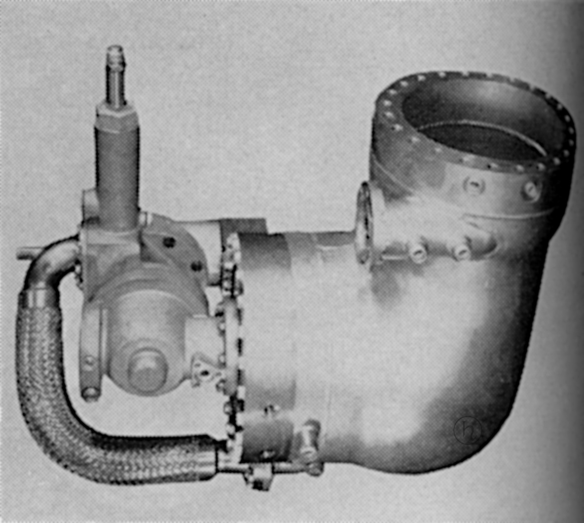
Photo of the F-1 gas generator circa March 1961.
Click image for a 1184x1059 pixel version of this image in a new window.
From page 46 of the March 1961 issue of Astronautics magazine,
"F-1 Engine Development", located in the Saturn V Collection, Dept. of Archives/Special
Collections, M. Louis Salmon Library, University of Alabama in
Huntsville.
Scan and cleanup by heroicrelics.
In an March 1961 article in Astronautics magazine, the gas generator of that time was described as operating fuel-rich and burning about 2% of the total propellants used in the engine. It was a partial sphere approximately 10 inches in diameter. That design made use of a double-wall combustion chamber, through which the fuel flowed to cool the body regeneratively. This feature added to the safety of the engine by eliminating a hot outer surface which could ignite leaking propellants, and it reduced heat radiation to adjacent components.
The main controls were four fuel valves integral to the thrust-chamber assembly, two oxidizer valves mounted on the thrust-chamber dome, a gas generator valve, a fuel- and oxidizer-flow regulator for the gas generator, and a four-way solenoid valve. This four-way solenoid valve was one of the only two components in the engine requiring electrical wiring or energy; the other was the spark exciter for gas generator ignition. The oxidizer and fuel valves were of the poppet type, which eliminated the turning moment associated with large butterfly and ball valves, simplified sealing problems, and minimized package size.
Gas generator tests were started on schedule in March 1960 with a successful short-duration test, and numerous successful tests were conducted without failures associated with the combustion process.
The gas generator was tested to the full facility capacity of 135 seconds and performed satisfactorily over wide ranges of mixture ratio, temperature, and pressure. Also included in the test series were simulated engine start sequences, demonstrating suitability of gas generators for engine use.
Gas Generator - August 1961
Even moreso than the example above, this incarnation of the gas generator shows a design heritage owing to the S-3D gas generator.
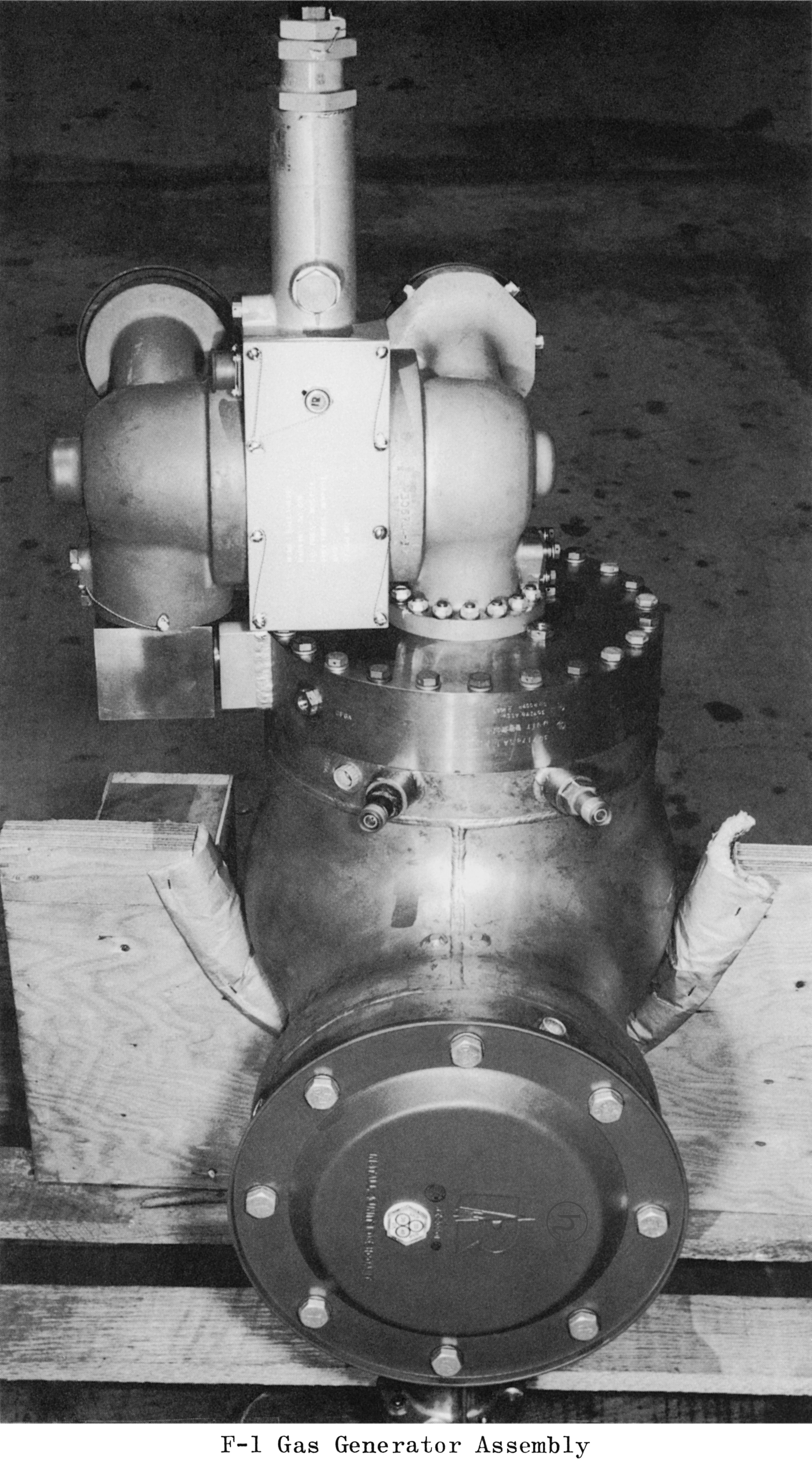
Photo of the F-1 gas generator circa August, 1961.
Click image for a 2847x5135 pixel version of this image in a new window.
From F-1 Design Information R-2823-1 (23 August 1961), in the
Dieter Huzel Collection of the archives of the U.S. Space &
Rocket Center.
Scan and cleanup by heroicrelics.
As of an August 1961 Rocketdyne report, the gas generator assembly was described as consisting of a body, injector, valve, manifolding, and associated plumbing. The body was still a lightweight, double-walled design which was regeneratively cooled by fuel. Gas generator propellant entry was controlled by a linked, dual ball valve, operated by a single actuator. Propellants were ignited by two semiconductor spark plugs mounted in the combustor body just below the injector face. The spark plugs were powered by a single exciter and equipped with a monitor system which indicated when a plug was firing satisfactorily.
Gas Generator - April 1965
By April 1965, the gas generator reached something very close to its final form, taking its familiar shape and losing its double-walled construction.
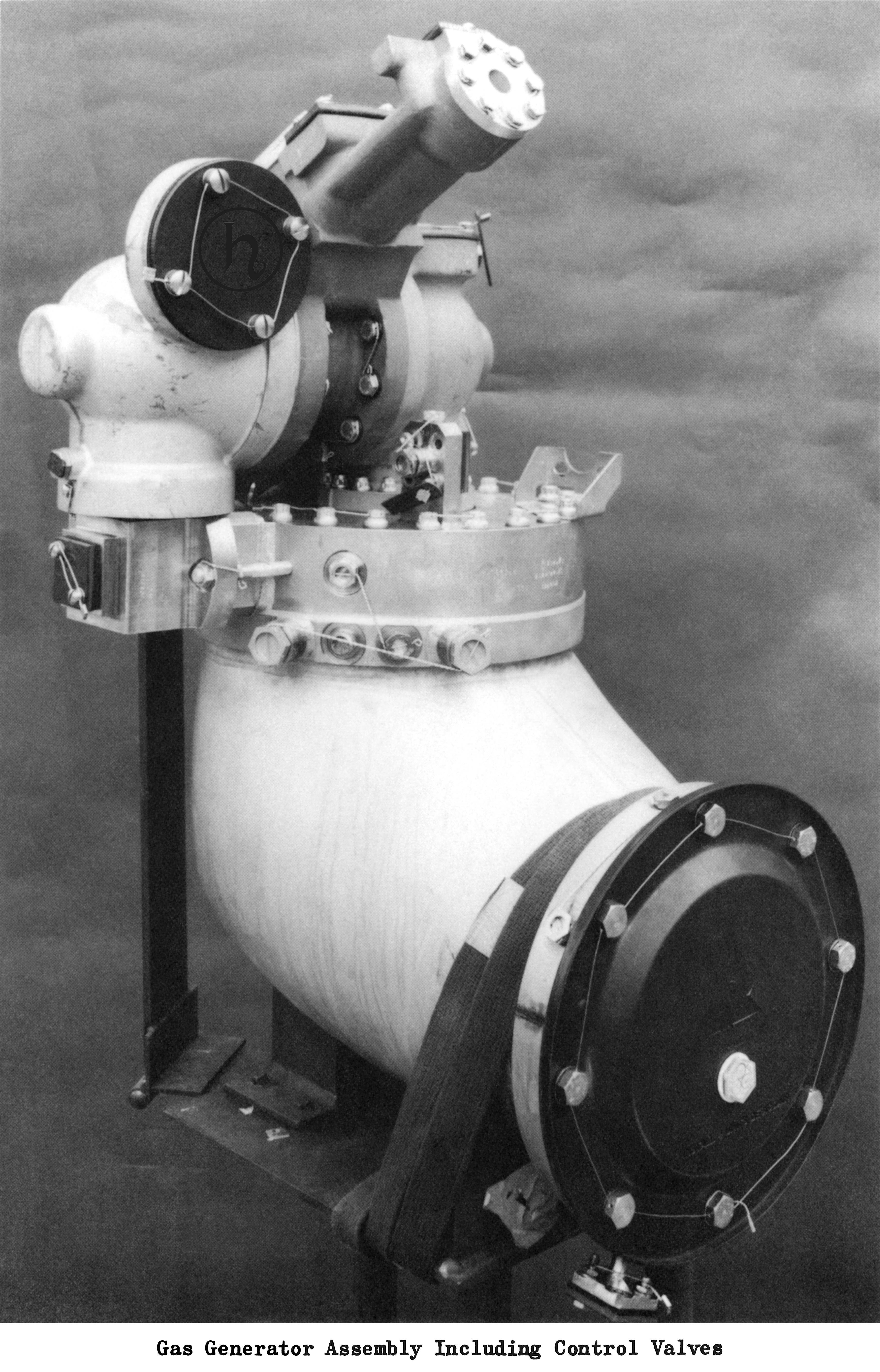
Photo of the F-1 gas generator circa April 1965.
Click image for a 3631x5659 pixel version of this image in a new window.
From page 11 of Saturn V Booster - The F-1 Engine by D.E. Aldrich.
Located in the Saturn V Collection, Dept. of Archives/Special
Collections, M. Louis Salmon Library, University of Alabama in
Huntsville.
Scan and cleanup by heroicrelics.
An April 1965 conference paper noted that the F-1 engine used a gas generator burning engine propellants at a fuel-rich mixture ratio to drive the turbine. The gas generator was 10 inches in diameter and burned propellants approximately at the equivalent rate of a 40,000-pound-thrust rocket engine. (As a point of comparison, the stock Redstone A-7 rocket engine produced a thrust of 75,000 lbs.) However, the mixture ratio was adjusted to produce much lower temperature combustion gas to be compatible with the turbine. The gas generator, like the turbine manifold, had an insulated outer shell to reduce heating of the engine compartment. Dual-linked ball valves admitted propellants to the gas generator.
The bulk of the descriptive text was taken, frequently verbatim or nearly so, from the F-1 Engine Familiarization Training Manual; F-1 Engine Training Aids, R-5991; and the Saturn V News Reference (August 1967). Text describing the gas generator development was largely taken from the works cited by the corresponding photo.