Return to U.S. Space & Rocket Center
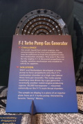
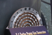
F-1 Engine Gas Generator Injector
In the past couple of years, the USSRC has put some really great (yet somewhat obscure) artifacts on display. One such exhibit which really got me excited was this F-1 engine gas generator injector.
The gas generator is essentially a smaller, inefficient rocket engine used to supply hot gas to the turbopump's turbine. The hot gas subsequently flows through the heat exchanger to heat gases to pressurize the propellant tanks and is ultimately used to provide film cooling for the nozzle extension.
The F-1 Rocket Engine Technical Manual: Engine Data (R-3896-1) describes the gas generator injector as follows:
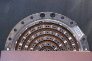
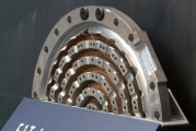
The gas generator injector is a flat-faced, multi-orificed-type injector incorporating a dome, a plate, a ring manifold, five oxidizer rings, five fuel rings, and a fuel disk. The injector is mounted on the combustor, and the gas generator ball valve and the gas generator fuel inlet housing tee are mounted on the injector. The injector directs fuel and oxidizer into the gas generator combustor. Fuel enters the injector through the gas generator fuel inlet housing tee from the gas generator ball valve. The fuel is directed through radial passages in the plate and injected into the combustor through orifices in the five fuel rings and the fuel disk. Oxidizer enters the injector through the oxidizer inlet manifold from the gas generator ball valve. The oxidizer is directed from the oxidizer manifold through internal passages in the plate and is injected into the combustor through the orifices in the five oxidizer rings. The injector uses a double-orificed pattern in which the fuel and oxidizer rings are drilled in a pattern and angle so that the stream from one oxidizer orifice will impinge upon the stream from another oxidizer orifice, and the stream from a fuel orifice will impinge upon the stream from another fuel orifice. Orifices in the outer fuel ring also provide a cooling film of fuel for the combustor choke ring wall.
Referring to the diagram of the gas generator injector on page 1-1 (p. 3 in the PDF) in my F-1 Rocket Engine Technical Manual Supplement (R-3896-1A), I believe the injector is actually exhibited with its back side to the public. At the 2:00 position is what appears to be the fuel inlet housing T interface. Areas are machined out of the silver oxidizer rings which match the decreasing diameter of the fuel passages shown in the upper right of the diagram on page 1-1.
Regardless of how it's exhibited, the USSRC is the only place I've ever visited which exhibits such an esoteric F-1 engine component!
 dsc73901.jpg |
 dsc73896.jpg |
 dsc73898.jpg |
 dsc74875.jpg |
 dsc74872.jpg |
 dsc74873.jpg |
 dsc74874.jpg |
 dsc82689.jpg |
 dsc82692.jpg |
Return to U.S. Space & Rocket Center