LR-101 Vernier Engine
Rocketdyne's LR-101 was a small, secondary (or "vernier") engine. Two LR-101s were mounted on the Atlas and Thor missiles (and, later, the Delta launch vehicle, by virtue of its first stage being a modified Thor missile). It was produced in several versions and operated under different conditions, but the LR-101 generally produced about 1,000 pounds of thrust. Later, in its Atlas Space Launch Vehicle configuration, its thrust was downrated as adequate roll and attitude control could be accomplished at a lower thrust rate and the corresponding lower propellant flowrate meant that more propellant was available to the sustainer engine, in turn producing improved overall launch vehicle performance.
On the Atlas, the two outer booster engines were gimballed; two gimballed engines allowed for yaw, pitch, and roll control. After about two minutes of flight, the boosters were jettisoned, leaving the single center sustainer engine. While this engine was also gimballed, roll control is not possible with only one engine. The primary purpose of the LR-101 vernier engines was to provide roll control after the booster engines had been jettisoned. They also contributed to thrust and, after the sustainer was shut down, powered the Atlas to its final velocity and position.
The LR-101 was a single-start, fixed-thrust engine with an expansion ration of 6:1. In its Block 2 version, ignition occurred by means of pyrophoric (hypergolic) fluid (a mixture of tri-ethyl aluminum and tri-ethyl boron) which ignites spontaneously in the presence of oxygen. The earlier Block 1 model was ignited pyrotechnically. (A former Rocketdyne employee contacted me after I initially put up this page saying that in the July 1956 to July 1957 timeframe, they were ignited "by a sparkler stuck in the throat". I don't know exactly when the Block 2 was introduced, but it appears to have been in use by mid-1960.)
The LR-101's thrust chamber weighed only about 15 pounds; in its -NA-15 configuration, the mount and bearing assembly added another 27 pounds.
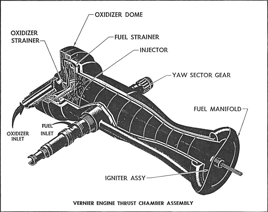
Here is a cut-away diagram of the LR-101 thrust chamber assembly:
Click image for a 1842x1459 pixel version of this image in a new window.
Scan by Aerocon Systems
Restoration by heroicrelics.
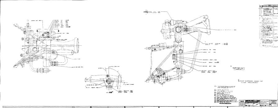
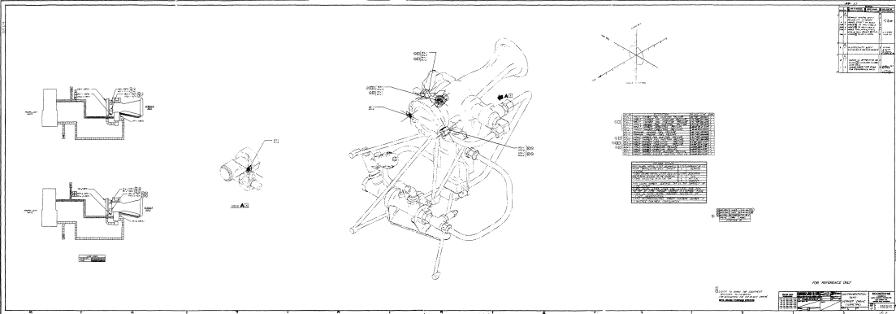
Here are a series of technical drawings of the LR-101-NA-11 (Thor) configuration.
First is "Customers Connection - Vernier Engine", Rocketdyne drawing #350723:
Click image for a 3893x1000 pixel version or click here for a 11559x2969
pixel version of this image in a new window.
Taken from Design
Information Report for the LV-2A Propulsion System (YLR79-NA-13 Main Engine and
LR101-NA-11 Vernier Engines), pages 23/24 (pages 59-64 of the
PDF).
Extraction, reconstruction, and restoration by heroicrelics.org.
"Oriface & Accessory Installation - Vernier Engine", Rocketdyne drawing #350670:
Click image for a 2576x1000 pixel version or click here for a 8108x3147
pixel version of this image in a new window.
Taken from Design
Information Report for the LV-2A Propulsion System (YLR79-NA-13 Main Engine and
LR101-NA-11 Vernier Engines), pages 11/12 (pages 37-40 of the
PDF).
Extraction, reconstruction, and restoration by heroicrelics.org.
"Instrumentation Taps - Vernier Engine (Isometric)", Rocketdyne drawing #350050:
Click image for a 2857x1000 pixel version or click here for a 8831x3091
pixel version of this image in a new window.
Taken from Design
Information Report for the LV-2A Propulsion System (YLR79-NA-13 Main Engine and
LR101-NA-11 Vernier Engines), pages 27/28 (pages 70-74 of the
PDF).
Extraction, reconstruction, and restoration by heroicrelics.org.
The following data sheet is also provided by Aerocon Systems:
LR101-NA-1
1000 lb. Thrust
THRUST. . . . . . . . . . . . . (NA-13) 669 ± 5% @ sea level, pump fed
(NA-15) 1000 ± 3% @ sea level, pump fedPROPELLANTS . . . . . . . . . . Liquid oxygen (MIL-P-25508C) and RP-1* (MIL-R-25576B) O/F WEIGHT RATIO. . . . . . . . 1.8 ± 0.1 RATED DURATION. . . . . . . . . 322.5 sec** (ATLAS), 184 sec (THOR) PROPELLANT FEED . . . . . . . . Sustainer engine turbopump until cutoff; thereafter they are tank fed THRUST VECTOR CONTROL . . . . . Gimbaled thrust chambers ± 75° yaw, -35° and -25° in pitch (ATLAS), ± 47° pitch, +6 and 34° yaw (THOR) CURRENT USE . . . . . . . . . . Verniers for ATLAS and THOR missiles STATUS. . . . . . . . . . . . . In production. Preliminary design was completed in June 1958 for the LR101-NA-3 SPONSORING AGENCY . . . . . . . U. S. Air Force through ATLAS and THOR contracts
RJ-1 (MIL-F-25558B) has been utilized in the LR101-NA-11325 sec for LR101-NA-7
PERFORMANCE (Sea Level) NA-13 NA-15 Md 1 NA-15 Md 2 Pump
Fed*Tank
FedPump
FedTank
FedPump
FedTank
FedThrust, lb 1000 830 669 526 913 777 Thrust Coefficient 1.33 1.30 1.247 1.171 1.307 1.281 Specific Impulse, lbf-sec/lbm nominal 207 197 190.5 183.9 205.3 197.6 minimum 200 194 Characteristic Exhaust Velocity, ft/sec 4997 4897 4915 5052 5053 4962 Chamber Pressure, psia 358 302 257 216 337 292 Fuel and Oxidizer Supply Pressure, psia 630 510 509 LOX 390 LOX 646 LOX 543 LOX 448 Fuel 335 Fuel 678 Fuel 543 Fuel Flow Rates, lb/sec Total 4.81 4.17 3.51 2.86 4.45 3.93 Oxidizer 3.09 2.68 2.22 1.84 2.81 2.53 Fuel 1.72 1.49 1.29 1.02 1.64 1.40
At altitudes above 100,000 ft, the thrust is approximately 1154 lb and specific impulse is 238 lbf-sec/lbm for the NA-13
While most Atlases on display lack their vernier engines, I have photographed a number of LR-101s, both stand-alone engines and engines installed in missiles:
- There's a stand-alone LR-101 displayed at the Air Force Space & Missile Museum (which, when I visited, was on Kennedy Space Center's "Then and Now" tour).
-
Mark Wells has a number of LR-101
engines and parts, including
- An LR-101 with full gimballing mechanism;
- A stand-alone LR-101 thrust chamber;
- And a cut-away LR-101 thrust chamber, showing the double-walled construction and coil welded between the thrust chamber walls.
- The Mercury-Atlas displayed at KSC still has its verniers.
- The Thor at Strategic Air & Space has intact verniers.
- The Delta in the Goddard Space Flight Center Rocket Park is displayed with its LR-101s.
- The Kansas Cosmosphere displays an Atlas vernier start tank.
Additional information on the LR-101 can be found in


