F-1 With Callouts
This page serves as a repository for photos and diagrams of the F-1 rocket engine with callouts identifying major (and even not-so-major) components. I have several more photos and diagrams which I intend on uploading once I clean them up.
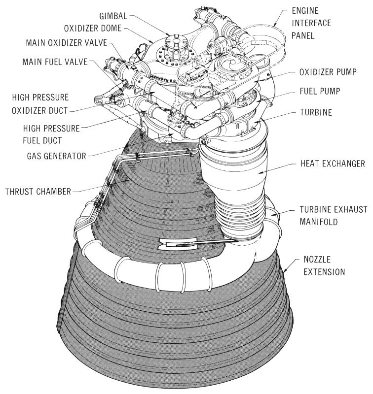
This diagram is from the Saturn V News Reference. It reflects an early F-1 configuration with internally tied propellant high-pressure ducts. After SA-501 (the Apollo 4 mission), the F-1s had rigid propellant high-pressure ducts. The rigid high-pressure ducts are easily identified as the fuel high-pressure ducts make a large "U" shape, rather than being straight as depicted here.
Click image for a 2448x2592 pixel version of this image in a new window.
From page 3-0 of the Saturn V News Reference. Located in the
Saturn V Collection, Dept. of
Archives/Special Collections, M. Louis Salmon Library, University of
Alabama in Huntsville.
Scan and clean-up by heroicrelics.
The engine components identified here include
- Gimbal
- Oxidizer Dome
- Main Oxidizer Valve
- Main Fuel Valve
- High Pressure Oxidizer Duct
- High Pressure Fuel Duct
- Gas Generator
- Thrust Chamber
- Engine Interface Panel
- Oxidizer Pump
- Fuel Pump
- Turbine
- Heat Exchanger
- Turbine Exhaust Manifold
- Nozzle Extension
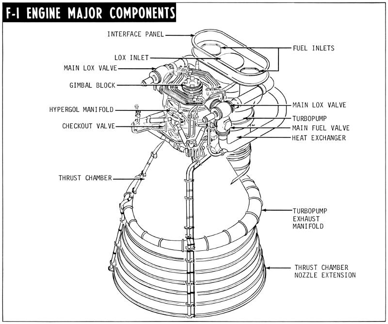
This diagram is from the Saturn V Flight Manual SA-509. It reflects the post-SA-501 (the Apollo 4 mission), F-1 configuration with rigid propellant high-pressure ducts. This diagram is also rotated approximately 90° compared to the diagram above.
Click image for a 4173x3492 pixel version of this image in a new window.
From page 4-6 of the Saturn V Flight Manual SA-509. Located in
the Mauldin Collection, Dept. of
Archives/Special Collections, M. Louis Salmon Library, University of
Alabama in Huntsville.
Scan and clean-up by heroicrelics.
The engine components identified here include
- Interface Panel
- LOX Inlet
- Main Fuel Valve
- Gimbal Block
- Hypergol Manifold
- Checkout Valve
- Thrust Chamber
- Fuel Inlets
- Main LOX Valve
- Turbopump
- Main Fuel Valve
- Heat Exchanger
- Turbopump Exhaust Manifold
- Thrust Chamber Nozzle Extension


