
F-1 Rocket Engine Main LOX Valve
This page serves as a repository for information, photos, and diagrams of the F-1 rocket engine's main LOX valve (sometimes called the main oxidizer valve).
The F-1 rocket engine had two identical main oxidizer valves, flange-mounted 180° apart on the oxidizer dome that directed the flow of liquid oxygen to the thrust chamber and the flow of hydraulic control opening fluid to the gas generator control valve. The oxidizer valves were high-flow, hydraulically-actuated, spring-loaded closed, pressure-balanced, fail-to-the-run position, poppet-type valves having quick response and low delta-P operating characteristics. An integral part of each oxidizer valve, and mechanically opened by this valve, was a normally closed sequence valve which, in the open position, directed hydraulic control fluid to the opening port of the gas generator control valve.
The valves each included a position indicating device. Also mounted to each valve was an oxidizer dome purge check valve.
In the following diagram, the LOX inlet is at the bottom; this is upside down compared to looking at the main LOX valve on an F-1 engine that is mounted on its dolly.
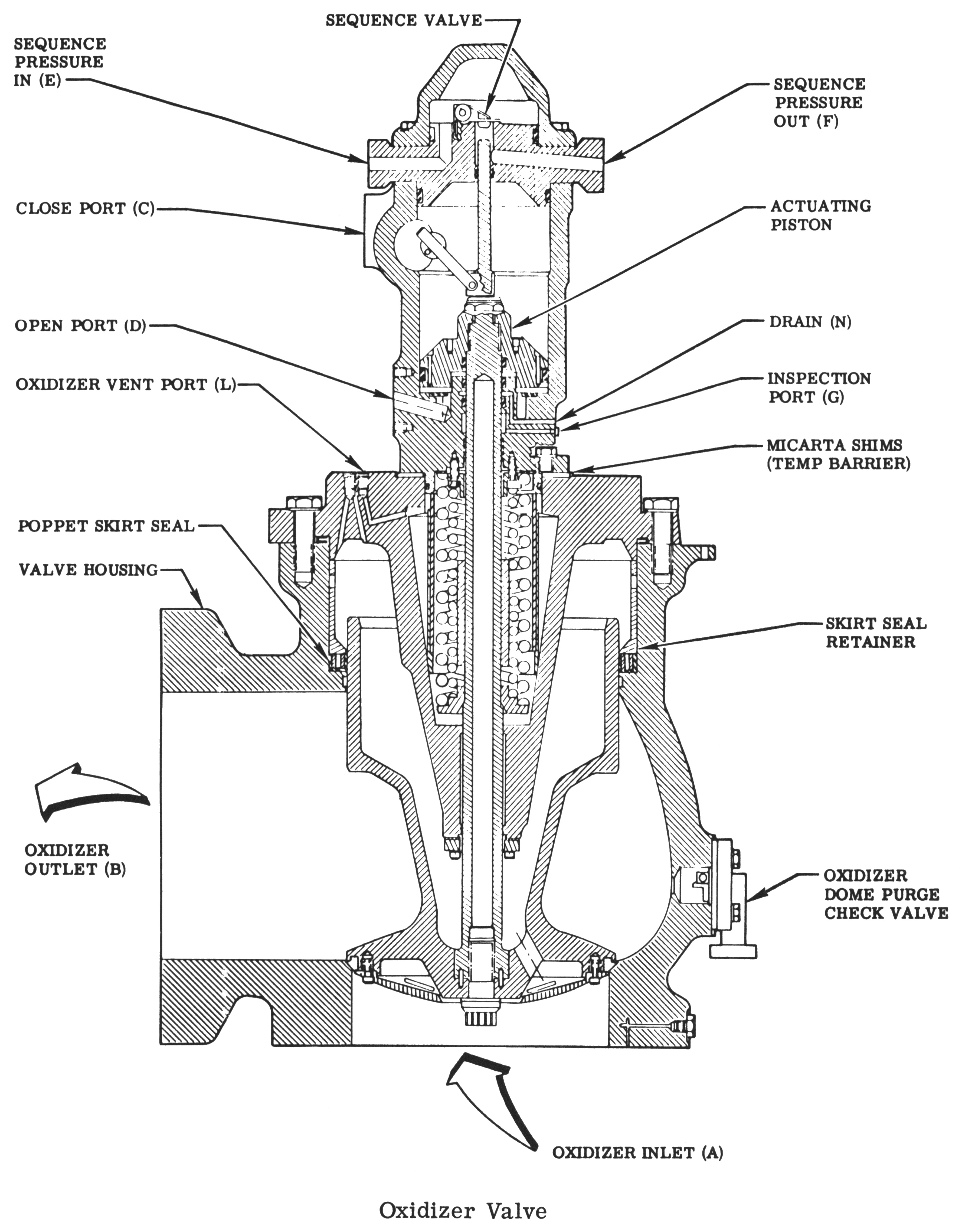
Cut-away diagram of an F-1 rocket engine main LOX/oxidizer valve.
Click image for a 3554x4500 pixel version of this image in a new window.
From page 1-20 of the F-1 Engine Familiarization Training Manual,
located in the archives of the U.S.
Space & Rocket Center. A superset of this document is also available
from archive.org.
Scan and cleanup by heroicrelics.
The oxidizer valve was designed so that when it was in the open position, at rated engine oxidizer pressure and flowrate, it would be held open by the flow of oxidizer even if hydraulic control fluid opening pressure was lost. The oxidizer valve consisted of a housing that contained the oxidizer inlet and outlet ports and the seat for the poppet seal; a poppet with a machined Teflon seal secured by a seal retainer; a cover that attached to the valve housing and contained the two poppet-closing springs and also served as a mount for the cylinder and a guide for the piston rod; a cylinder, within which the actuating piston operated, that contained the open and closed actuator ports and supported the position indicator drive shaft; a cylinder head that contained the inlet and outlet ports of the sequence valve and also provided a mount for the sequence valve gate; and a tapered piston rod that connected the actuator to the poppet, mechanically opened the sequence valve, and actuated the position indicator.
The sequence valve was a spring-loaded gate valve that seated against, and was hinged to, the oxidizer valve cylinder head. The sequence valve was offseated by the piston rod to direct opening hydraulic control fluid to the gas generator control valve when the oxidizer valve reached 16.4 percent of its open position. The position indicator consisted of a rotary-motion variable resistor and open and closed position switches. The position indicator was mounted on the oxidizer valve cylinder and was coupled to the indicator drive shaft, which was mechanically linked to the piston rod. The position switch provided relay logic in the engine electrical control circuit, and the variable resistor provided instrumentation for recording valve poppet movement.

Click image for a 5741x4541 pixel version of this image in a new window.
From p. 42 of F-1 Engine Training Aids, R-5991, in the Dieter
Huzel Collection of the archives of the U.S.
Space & Rocket Center.
Scan and clean-up by heroicrelics.
Each oxidizer valve incorporated an oxidizer dome purge check valve to admit gaseous nitrogen downstream of the valve poppet to purge the thrust chamber oxidizer dome. The check valve was a gate-type valve, spring loaded to the closed position, and allowed flow in one direction when the differential pressure across the valve exceeded 5.0 psi. Five types of seals were used in the oxidizer valve: machined Teflon seals, Mylar lip seals, Teflon-coated steel Naflex seals, and Buna-N O-rings.
The main oxidizer valves were the first valves to be opened during an engine start sequence and, through the sequence valves, controlled the opening of the gas generator ball valve.
The bulk of the descriptive text was taken, largely verbatim, from the F-1 Engine Familiarization Training Manual and from F-1 Engine Training Aids, R-5991.