
F-1 Rocket Engine Heat Exchanger
The F-1 rocket engine's heat exchanger was part of the gas generation system which powered the engine. Exhaust from the gas generator, after spinning the turbopump's turbines, was routed through the heat exchanger, where heat was extracted from the gas to expand gases used for vehicle tank pressurization.
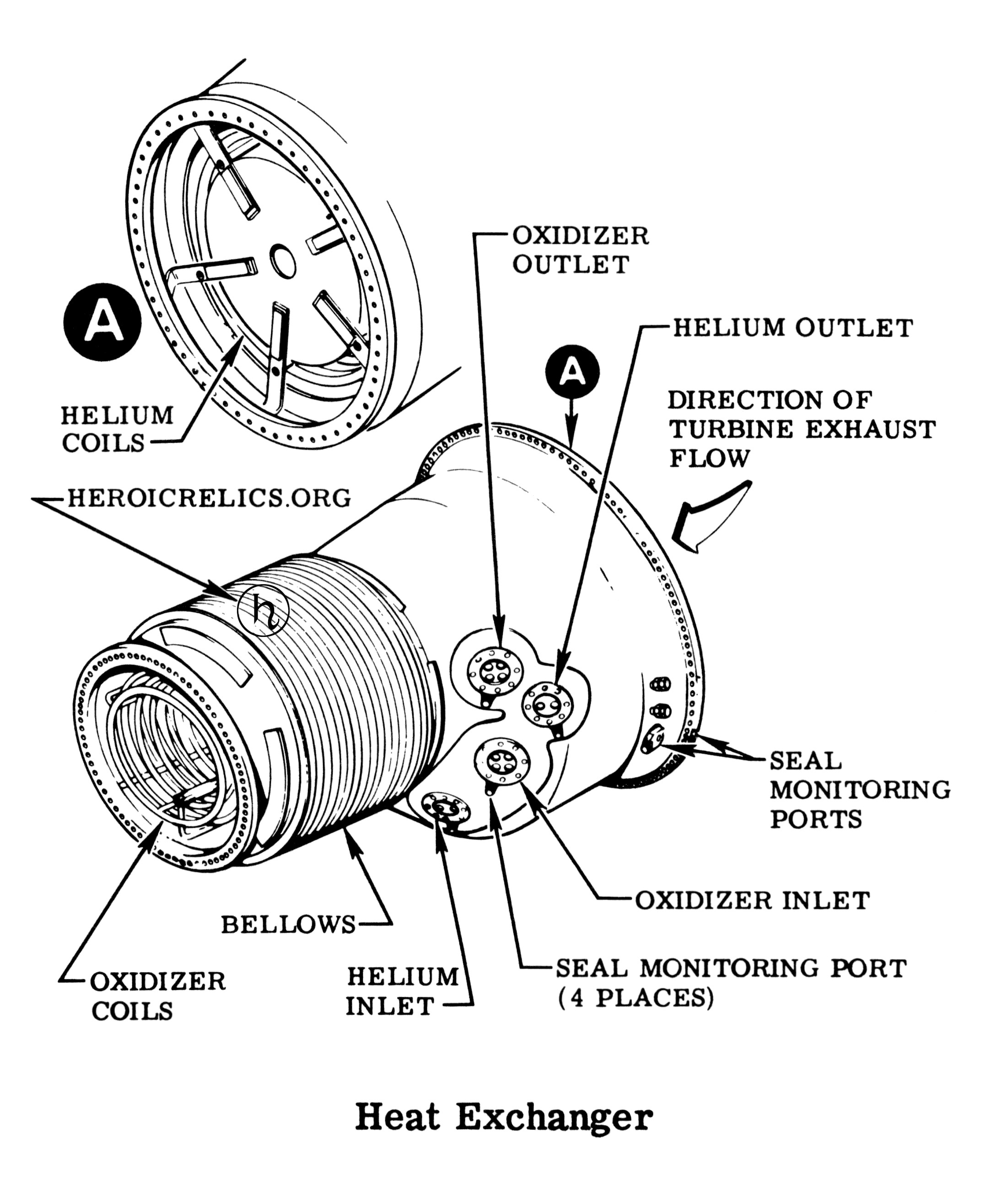
Diagram of an F-1 rocket engine heat exchanger, including its inlet, helium
coils, oxidizer coils, and inlets/outlet ports.
Click image for a 2203x2610 pixel version of this image in a new window.
From page 1-29 of the F-1 Engine Familiarization Training Manual,
located in the archives of the U.S.
Space & Rocket Center. A superset of this document is also available
from archive.org.
Scan, cleanup, and adaptation by heroicrelics.
After exiting the heat exchanger, the relatively cool exhaust gas was directed into the turbine exhaust manifold where it subsequently entered the double-walled nozzle extension, providing film cooling to protect the nozzle extension from the heat of the main thrust chamber's exhaust gases.
The heat exchanger was installed between the turbine outlet and the turbine exhaust gas manifold inlet. It weighed 825 pounds, was 58 inches long, and fit into a basic envelope of 43 inches in diameter, with the diameter varying from 40 inches at the turbine outlet and 24 inches at the turbine exhaust manifold. The heat exchanger shell incorporated a bellows assembly to compensate for thermal expansion during engine operation.
Contained inside and supported by the shell was a four-coil oxidizer pack and a two-coil helium pack. The turbine exhaust gas passed over the coils, although as shown in the diagram above, the heat exchanger inlet had some sort of a plate which blocked the direct flow of most of the turbine exhaust gas; I speculate that this is to help shield the coils from the direct jet blast of the gas (of course, the jet blast would be attenuated somewhat after passing through the two-stage turbine in the turbopump). Here is a photo of this plate on one of the recovered F-1 engine's heat exchanger while it was under conservation at SpaceWorks.
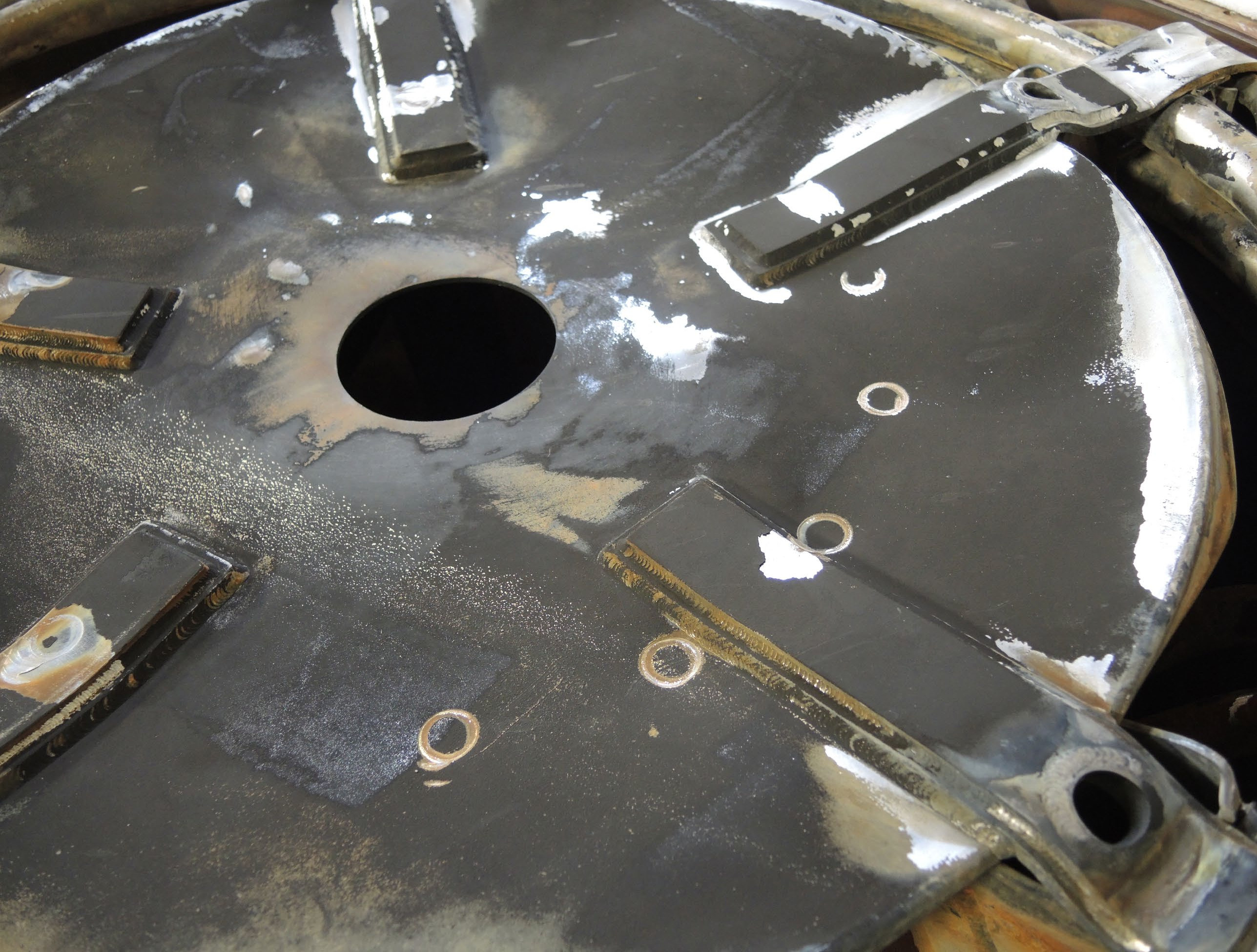
Recovered F-1 rocket engine heat exchanger inlet.
Click image for a 2575x1951 pixel version of this image in a new window.
From page 130 (page 9 in the PDF) of "One
Small step for Man, One Giant Leap for Conservation."
Extraction by heroicrelics.
High-pressure liquid oxygen from the LOX dome flowed through the oxidizer coil pack, was heated to gaseous oxygen (GOX), and was used to pressurize the vehicle oxidizer tank. (On my S-IC Major Components page, the GOX lines from the engines to the LOX tank are #21, and the GOX distributor at the top of the tank is #2.) A flowmeter measured the volume of LOX being delivered to the heat exchanger, and orifice plates, calibrated for each engine, controlled the amount of LOX admitted to the heat exchanger (and thus determined the amount of GOX pressurant produced). A bypass hose routed excess LOX from the supply port directly to the return port.
Tubular structural members, clamped to the coils and welded to brackets incorporated in the heat exchanger body, secured and restrained the oxidizer coils.
Cold helium, supplied from bottles stored in the LOX tank (#23 in my S-IC Major Components page), passed through the other coil pack, where it was heated and expanded for use in pressurizing the vehicle fuel tank via a helium line (#22) to a helium distributor (#24) at the forward end of the tank. Like the LOX supply, the inlet port used orifice plates to control the amount of helium entering the heat exchanger and a bypass hose to route excess helium to the return line.
The following photo shows the oxygen and helium supply and return ports, as well as the bypass hoses.
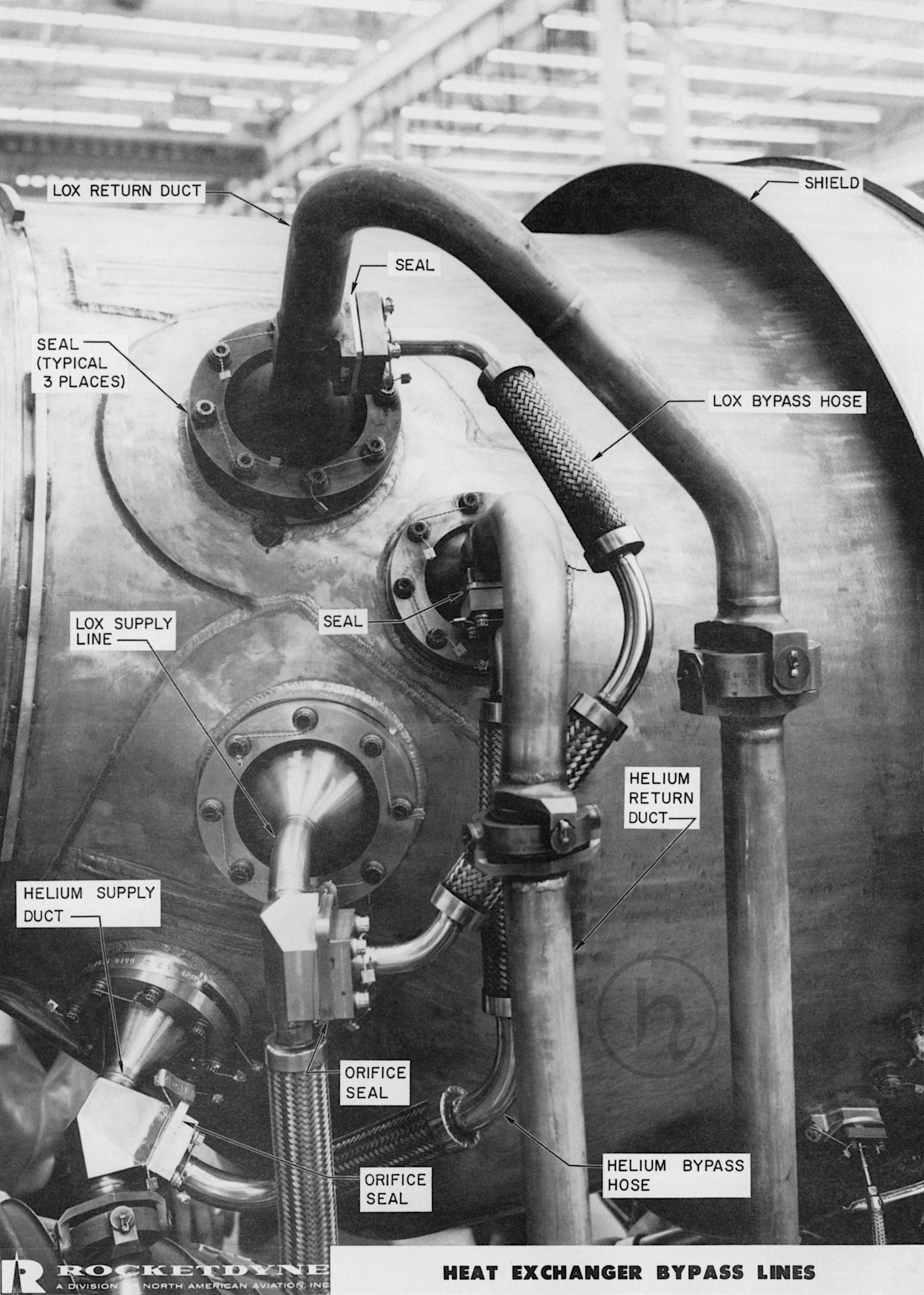
F-1 rocket engine heat exchanger supply, return, and bypass lines.
Click image for a 4370x6126 pixel version of this image in a new window.
From page 34 of the F-1 Engine Training Aids, R-5991, located in
the archives of the
U.S. Space & Rocket Center.
Scan and cleanup by heroicrelics.
During normal engine operation (usually achieved after about 35 seconds of engine operation), the heat exchanger expanded approximately 0.6 pounds of helium per second at an inlet temperature of approximately -345°F and raised the temperature to 255°F. It expanded approximately 4.0 pounds of LOX per second at an inlet temperature of approximately -288°F to gaseous oxygen, raising the temperature to about 470°F.
The bulk of the descriptive text was taken, frequently verbatim or nearly so, from the F-1 Engine Familiarization Training Manual and F-1 Engine Training Aids, R-5991.