
F-1 Engine Cut-Aways
I've collected a number of F-1 rocket engine cut-away diagrams for this page. I was originally going to use these diagrams as a take-off point to discuss various features of the engine, but the resulting page wound up being huge. I will, therefore, refer to you to my F-1 thrust chamber, F-1 injector, and F-1 injector baffles pages. All that remains on this page are several gratuitous F-1 rocket engine cut-away diagrams.
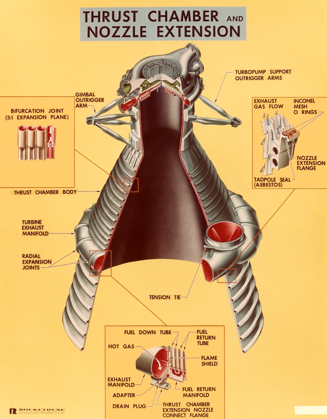
Thrust Chamber and Nozzle Extension
This diagram shows a cut-away of the overall thrust chamber and its interface with the nozzle extension:
Click image for a 1101x1408 pixel version of this image in a new window.
Photo courtesy Vince
Wheelock.
For a detailed description of the combustion chamber, as well as many fabrication/assembly photos, see my F-1 engine thrust chamber page.
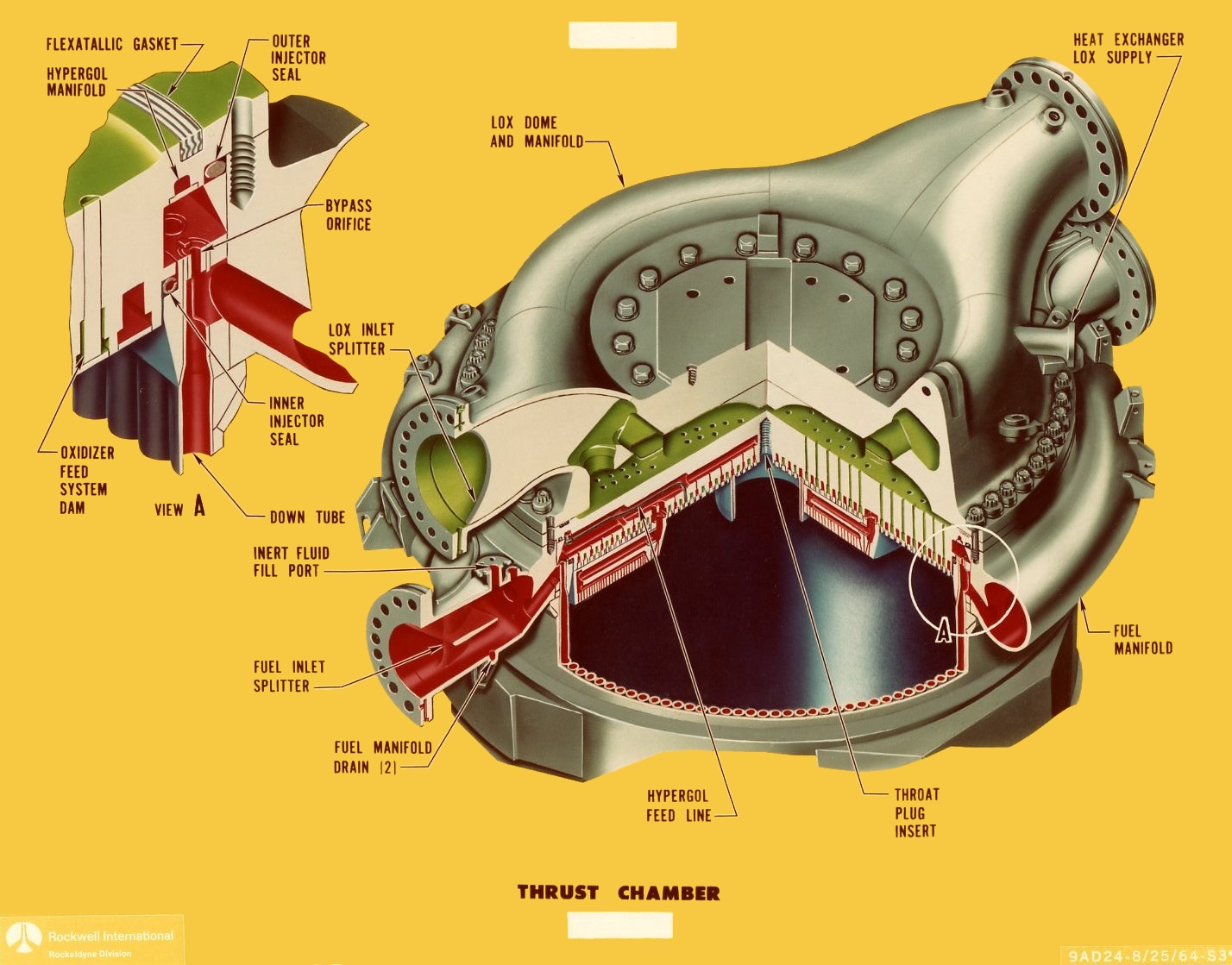
Injector End
This cut-away diagram depicting the F-1 injector end, as is typical of color diagrams of rocket engine internals, represents LOX flow as green and fuel flow as red:
Click image for a 1428x1119 pixel version of this image in a new window.
Photo courtesy Vince
Wheelock.
Cleanup by heroicrelics.
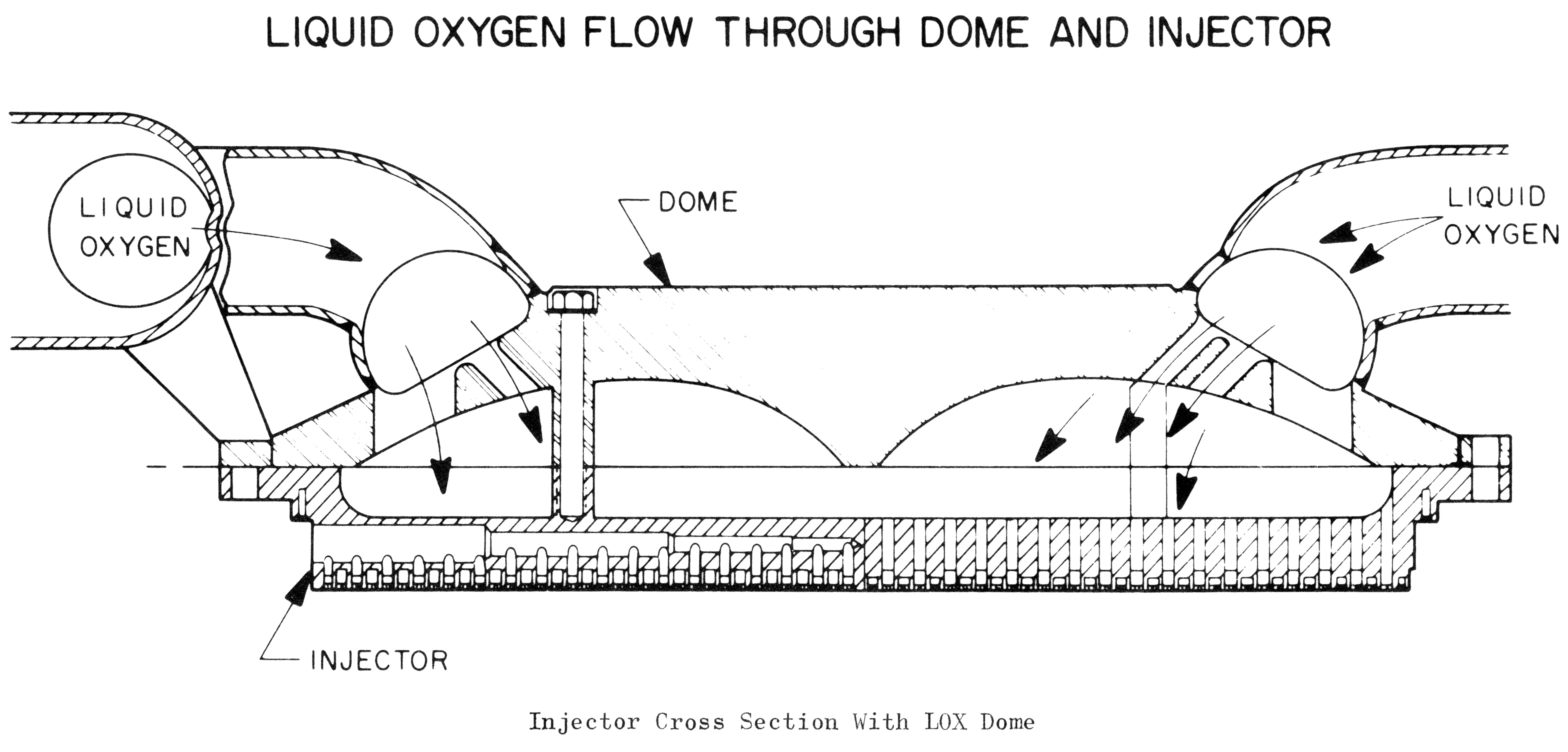
This diagram, from a paper which seems to date from sometime before July 1967, shows another view of the injector. I'm not certain why this diagram lacks a number of features of the other injector cut-aways; my best guess is that this particular diagram was unclassified back in the day, while the other diagrams were still classified at the time. This diagram does give a better feel for the LOX flow.
Click image for a 5526x2651 pixel version of this image in a new window.
From Saturn V Booster - The F-1 Engine by D.E. Aldrich. Located
in the Saturn V Collection, Dept.
of Archives/Special Collections, M. Louis Salmon Library, University of
Alabama in Huntsville.
Scan and cleanup by heroicrelics.
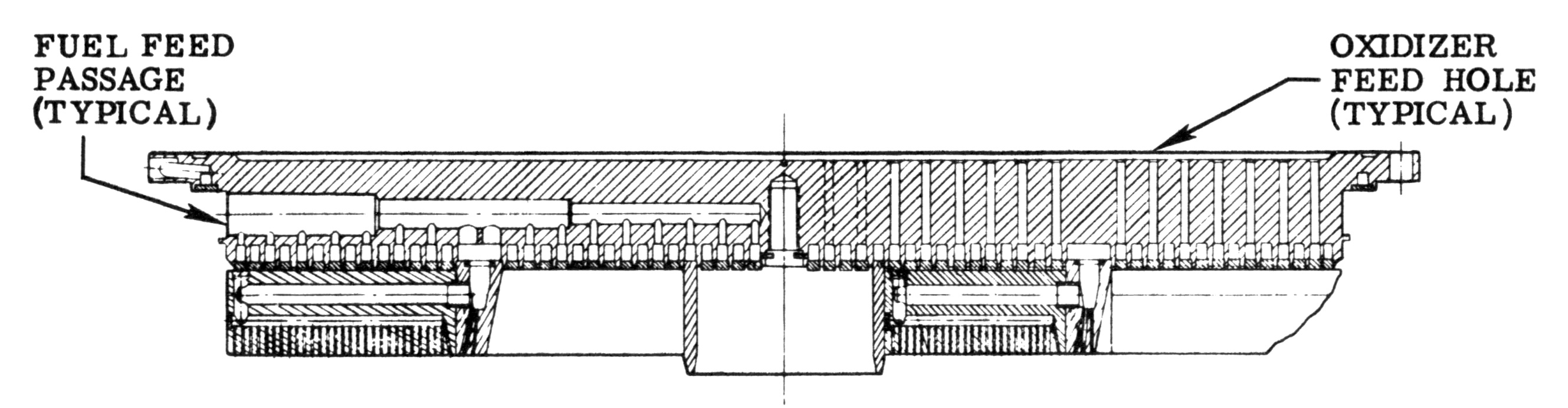
This final injector cut-away diagram clearly shows how the radial injector baffles are regeneratively cooled, with the feed line leading from the fuel feed passage, through the radial baffles, and finally to the radial baffles themselves:
Click image for a 2658x691 pixel version of this image in a new window.
Adapted from p. 1-2 of the F-1 Rocket Engine
Technical Manual Supplement (R-3896-1A)
Adaptation by heroicrelics.
See my F-1 engine injector and F-1 engine injector baffle pages for additional information about the injector, the hypergol feed line, and the injector baffles.