
Service Module Overview
The Service Module was a cylindrical structure which served as a storehouse of critical subsystems and supplies for most of the duration of an Apollo mission. It was attached to the Command Module from launch until shortly before Earth atmospheric entry.
The Service Module contained the spacecraft's main propulsion engine, which was used to brake the spacecraft to put it into lunar orbit and to send it on the homeward journey from the moon. The engine was also used to correct the spacecraft's course on the trip to and from the moon.
Besides the service propulsion engine and its propellant and helium tanks, the Service Module contained a major portion of the electrical power, environmental control, and reaction control subsystems, as well as various communications subsystems.
About 75% of the Service Module's weight consisted of propellant for the Service Propulsion System engine.
Click image for a 2584x3726 pixel version of this image in a new window.
Composite diagram based on page 57 of the Apollo Spacecraft News
Reference [Command/Service Module], located in the Saturn V collection,
Dept. of Archives/Special
Collections, M. Louis Salmon Library, University of Alabama in Huntsville
(a similar-vintage News Reference is available in electronic
format from the Apollo Lunar
Surface Journal; refer to page 62 of that PDF) and page 135 of the
Apollo 15 Press Kit, located in the "Apollo 14 Collection and
Misc Material" collection, also at the UAH archives (also available in
electronic format from the heroicrelics
mirror of the Kennedy Space Center Library press kit page).
Scans and adaptation by heroicrelics.
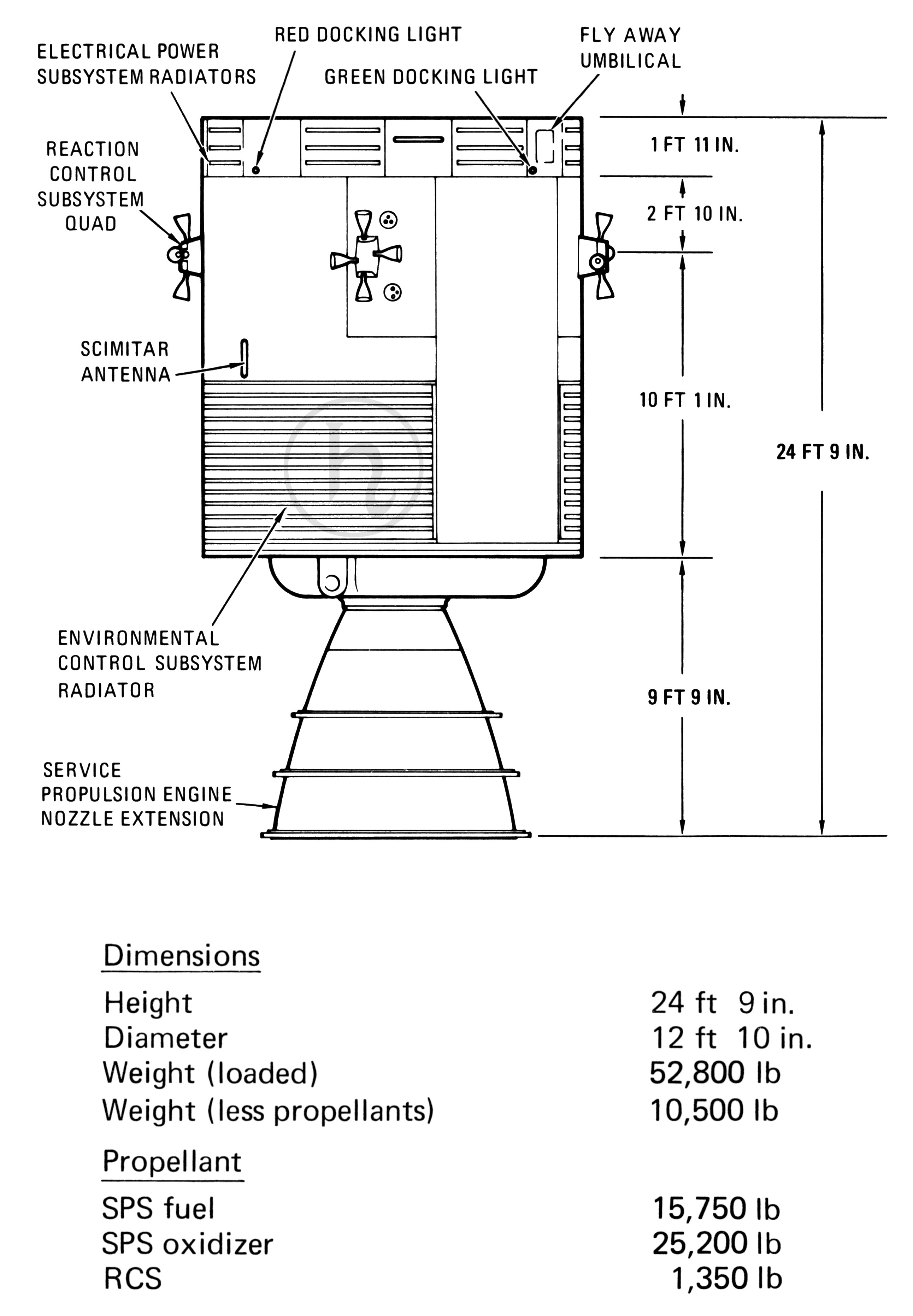
The callouts on this diagram include
- Fly Away Umbilical
- Green Docking Light
- Red Docking Light
- Electrical Power Subsystem Radiators
- Reaction Control Subsystem Quad
- Scimitar Antenna
- Environmental Control Subsystem Radiators
- Service Propulsion System Nozzle Extension
The diagram contains various weights and measures of the Service Module:
| Dimensions | |
|---|---|
| Height | 24 ft. 9 in. |
| Diameter | 12 ft. 10 in. |
| Weight (loaded) | 52,800 lb. |
| Weight (less propellants) | 10,500 lb. |
| Propellant | |
| SPS fuel | 15,750 lb. |
| SPS oxidizer | 25,200 lb. |
| RCS | 1,350 lb |
Additionally, the following individual dimensions are noted:
| Height of EPS Radiators | 1 ft. 1 in. |
| EPS Radiators to Middle of Quad | 2 ft. 10 in. |
| Middle of Quad to Aft Bulkhead | 10 ft. 1 in. |
| Aft Bulkhead to SPS Engine Exit Plane | 9 ft. 9 in. |
The mathematically-minded reader will note that the sum of the individual dimensions is 24' 7", while the overall height is listed as 24' 9". This is a composite diagram which I created, combining information from two separate sources, published a few years apart, so that may explain the discrepancy (although I suppose the missing two inches may be the thickness of the lines on the diagram, or perhaps the 24' 7" figure is due to compression when the Service Module is resting vertically on its SPS engine :-)
The Service Module's structure consisted of a center section or tunnel surrounded by six pie-shaped sectors, separated by six radial beams.
The radial beams were made of a solid aluminum alloy which was machined and chem-milled (metal removed by chemical action) to thicknesses varying between 2 inches and 0.018 inch, thus making a lightweight, efficient structure. Bolted to the radial beams were four sector panels, which were one inch thick and made of aluminum honeycomb core between two aluminum face sheets
Click image for a 2013x2359 pixel version of this image in a new window.
Composite diagram based on page 57 of the Apollo Spacecraft News
Reference [Command/Service Module], located in the Saturn V collection,
Dept. of Archives/Special
Collections, M. Louis Salmon Library, University of Alabama in
Huntsville (a similar-vintage News Reference is available in
electronic format from the Apollo Lunar
Surface Journal; refer to page 62 of that PDF) and page 135 of the
Apollo 15 Press Kit, located in the "Apollo 14 Collection and
Misc Material" collection, also at the UAH archives (also available in
electronic format from the heroicrelics
mirror of the Kennedy Space Center Library press kit page).
Scan and adaptation by heroicrelics.
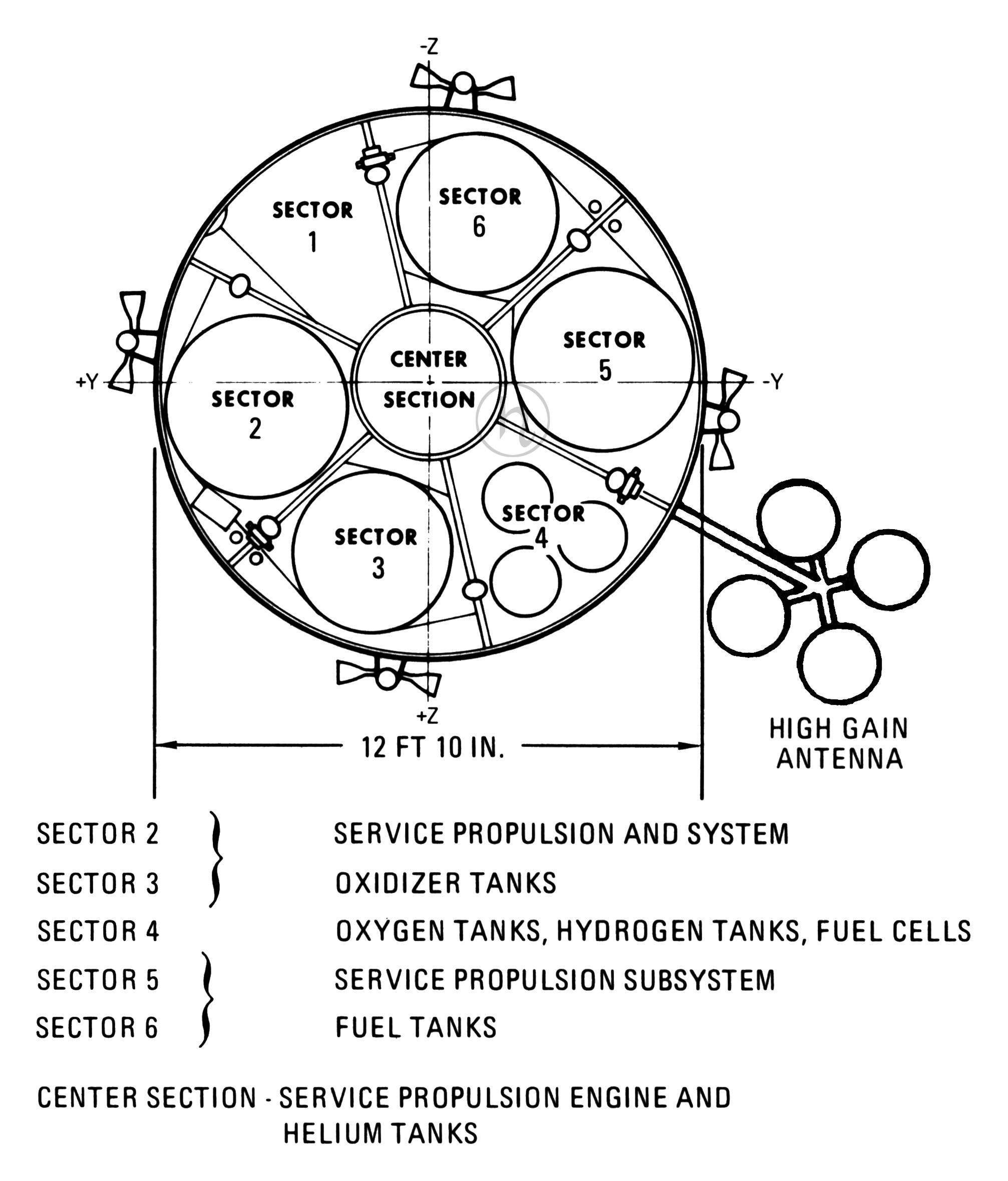
The +Y, -Y, +Z, and -Z axes of the spacecraft are marked. For reference, the crew entrance hatch is on the -Z side of the spacecraft and the umbilical, sextant, and scanning telescope are on the +Z side of the spacecraft.
The diagram notes the contents of the various Service Module sectors:
| Sector 2 | } | Service Propulsion and System |
| Sector 3 | Oxidizer Tanks | |
| Sector 4 | Oxygen Tanks, Hydrogen Tanks, Fuel Cells | |
| Sector 5 | } | Service Propulsion Subsystem |
| Sector 6 | Fuel Tanks | |
| Center Section | Service Propulsion Engine and Helium Tanks | |
The sectors differed in size, with two sectors each of three different sizes. The 360 degrees around the center section were divided among two 50-degree (Sectors 1 and 4), two 60-degree (Sectors 3 and 6), and two 70-degree (Sectors 2 and 5) compartments.
Sector 1: Originally, this 50-degree sector was reserved for future expansion, with no equipment placed in this sector. After the Apollo 13 explosion, a third oxygen tank was installed in Sector 1; note that this is on the opposite side of the spacecraft from the other two oxygen tanks, providing an additional measure of redundancy. Additionally, this third tank included an isolation valve allowing it to be isolated from the fuel cells and from the other two tanks, so that in an emergency it could be used solely to feed the Command Module environmental control system.
Starting with Apollo 15, the Scientific Instrument Module (SIM) bay was installed in aft portion of Sector 1.
Sector 2: One of the two 70-degree sectors, Sector 2 contained part of a space radiator and a reaction control subsystem engine quad on its exterior panel, and the oxidizer sump tank, its plumbing, and the reaction control engine tanks and plumbing within the sector.
The oxidizer sump tank was the larger of the two tanks that held the oxidizer (nitrogen tetroxide) for the Service Propulsion Engine. A cylindrical tank made of titanium, it was 1 53.8 inches high (about 12' 9 ¾") and had a diameter of 51 inches (4' 3"). It held 1 3,923 pounds of oxidizer and was the tank from which oxidizer was fed to the engine. Feed lines connected the sump tank to the Service Propulsion Engine and to the oxidizer storage tank.
Sector 3: A 60-degree sector, Sector 3 contained the rest of the space radiator and a reaction control engine quad on its exterior panel, and the oxidizer storage tank and its plumbing within the sector.
The oxidizer storage tank was similar to the sump tank, although not as large. It was 154.47 inches high (about 12' 10½") and had a diameter of 45 inches. It held 11,284 pounds of oxidizer. Oxidizer was fed from the oxidizer storage tank to the oxidizer sump tank in Sector 2.
Sector 4: This 50-degree sector contained most of the electrical power subsystem equipment in the Service Module, including three fuel cells, two cryogenic oxygen and two cryogenic hydrogen tanks, and a power control relay box. A helium servicing panel was also located in this sector.
The three fuel cell powerplants were mounted on a shelf in the upper third of the sector. Each powerplant was 44 inches high, 22 inches in diameter, and weighed about 245 pounds. They supplied most of the electrical power for the spacecraft as well as some of the drinking water.
The cryogenic tanks supplied oxygen to the environmental control subsystem and oxygen and hydrogen to the fuel cell powerplants. The tanks were spherical, with the oxygen tanks mounted side by side in the center of the sector and the hydrogen tanks mounted below them one on top of the other.
The oxygen tanks were made of Inconel (a nickel-steel alloy) and were just over 26 inches in diameter. Each held 326 pounds of supercritical oxygen (a semi-liquid, semi-gas state). Operating temperature of the tanks ranged from -300° to 80°. Oxygen must be maintained at -297° to remain liquid.
The hydrogen tanks were made of titanium and were about 31 ¾ inches in diameter. Each held just over 29 pounds of hydrogen. (Recall that hydrogen is less dense than oxygen, requiring larger vessels to hold a smaller mass). The hydrogen was also supercritical, with the tank's operating temperature ranging from -425° to 80°. To remain liquid, hydrogen must be maintained at -423°.
After Apollo 13, a 400-ampere-hour silver oxide/zinc non-rechargeable battery weighing 135 pounds was added to Sector 4 to serve as a backup in case of fuel cell failure. This battery was identical to the four Lunar Module descent stage batteries.
High Gain Antenna is located between Sectors 4 and 5.
Sector 5: Another 70-degree sector, Sector 5 contained part of an environmental control radiator and a reaction control engine quad on the exterior panel, and the fuel sump tank within the sector.
The fuel sump tank occupied almost all of the space with the sector. It was a cylindrical tank made of titanium and was the same size as the oxidizer sump tank (153.8 inches high or 12' 9¾") and 51 inches in diameter. It held 8,708 pounds of Aerozine 50 (a 50-50 mixture of hydrazine and unsymmetrical dimethylhydrazine [UDMH]) for the Service Propulsion System engine. It was the tank from which the fuel was fed to the engine; feed lines also connected it to the fuel storage tank.
Sector 6: The other 60-degree sector contained the rest of the space radiator and a reaction control engine quad on its exterior, and the fuel storage tank within the sector.
The fuel storage tank was the same size as the oxidizer storage tank (154.47 inches [12' 10 ½"] high and 45 inches in diameter) and held 7,058 pounds of fuel. Fuel was fed from it to the fuel sump tank in Sector 5.
Although the sump and the storage tanks for fuel and oxidizer were the same size, the oxidizer was more than 50% heavier than the fuel, leading to the difference in the weight of each propellant.
Center Section: The center section or tunnel contained two helium tanks and the Service Propulsion System engine.
The helium tanks were spherical vessels about 40 inches in diameter positioned one on top of the other in the forward half of the center section. Each held 19.6 cubic feet of helium gas under a pressure of 3600 psi. This gas was used to pressurize the oxidizer and fuel tanks of the service propulsion subsystem. The pressure forced the propellant from one tank to another and through the feed lines to the engine.
The Service Propulsion System engine was located in the aft half of the center section, with its nozzle extension protruding more than 9 feet below the aft bulkhead of the module. The length of the engine including the skirt was 152.82 inches (about 12' 8") and its weight was 650 pounds. This engine was used as a retrorocket to brake the spacecraft and put it into orbit around the moon, to supply the thrust for the return to Earth from the moon, and for course corrections while travelling to and from the moon.
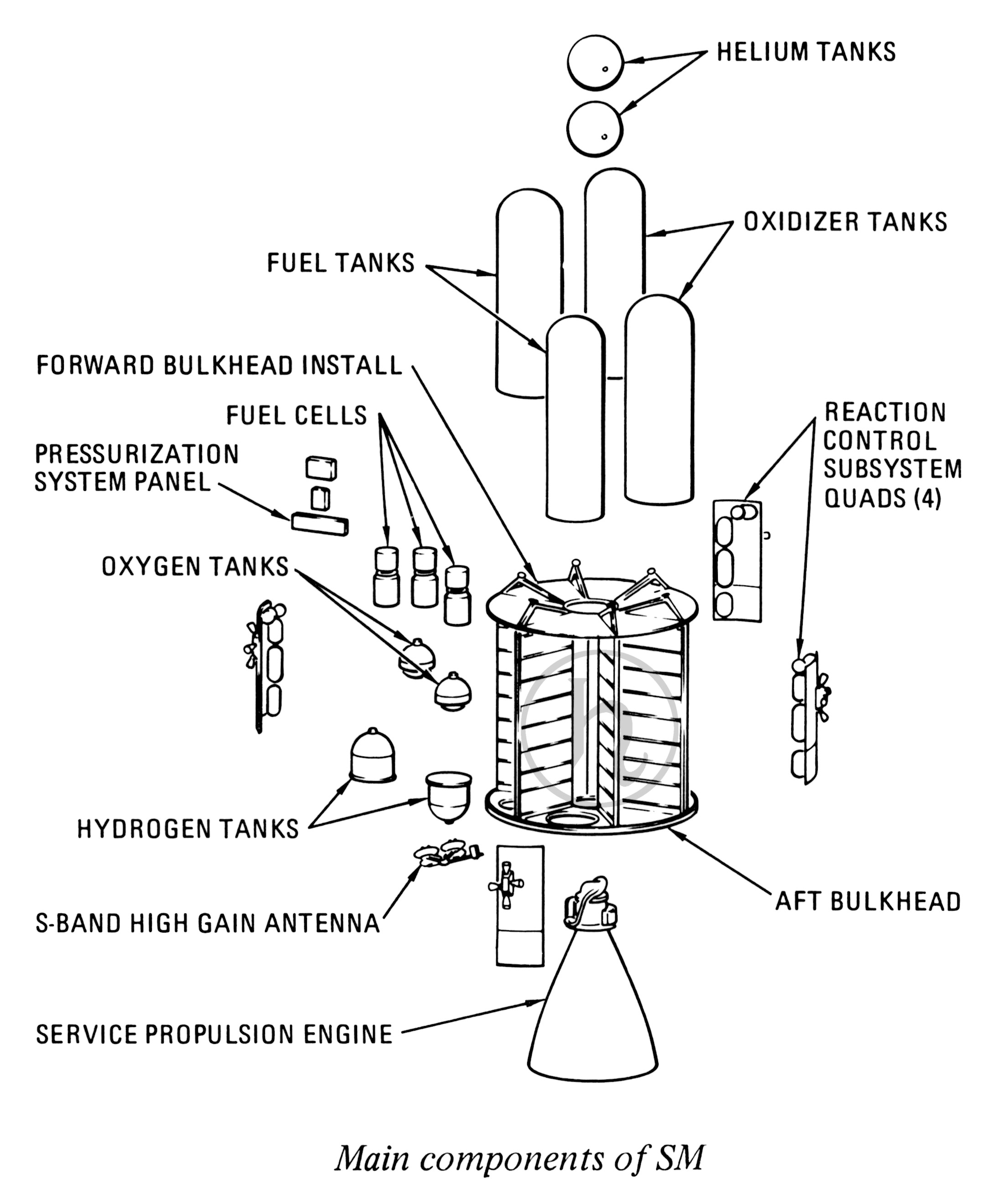
Click image for a 2184x2639 pixel version of this image in a new window.
From page 59 of the Apollo Spacecraft News Reference [Command/Service
Module], located in the Saturn V collection, Dept. of Archives/Special
Collections, M. Louis Salmon Library, University of Alabama in
Huntsville. A similar-vintage News Reference is available in
electronic format from the Apollo Lunar
Surface Journal; refer to page 62 of that PDF.
Scan and adaptation by heroicrelics.
Radiators for both the environmental control and electrical power subsystems were located on the exterior of the Service Module, as were reaction control subsystem engines, four antennas, umbilical connections, and several lights.
The environmental control subsystem radiators were the larger panels mounted on the aft half of the Service Module on opposite sides. One was part of the panel covers for Sectors 2 and 3 and the other was part of the panel covers for Sectors 5 and 6. The radiators, each about 30 square feet, consisted of five parallel primary tubes and four secondary tubes mounted horizontally and one series tube mounted vertically. The water-glycol coolant flowed through these tubes to radiate heat from the Command Module cabin and operating electronic equipment to the cold of space.
The electrical power subsystem radiators were located on the fairing at the forward end of the Service Module. Each of the eight radiators (which alternated with eight aluminum honeycomb panels) contained three tubes which were used to radiate excess heat produced by the fuel cell powerplants. A separate radiation loop was used for each powerplant; that is, one of the tubes on each panel was connected to a specific powerplant.
The four antennas on the outside of the Service Module were the S-band high gain antenna on the aft bulkhead; two VHF omni-directional antennas, mounted on opposite sides of the Service Module near the top; and the rendezvous radar transponder antenna, mounted in the SM fairing. The S-band high gain antenna, used for deep space communications, was composed of four 31-inch diameter reflectors surrounding an 11-inch square reflector. At launch it was folded down parallel to the Service Propulsion System engine nozzle so that it fit within the Spacecraft-Lunar Module Adapter.
The omni-directional antennas, called scimitars because of their shape, were made of stainless steel and were approximately 13.5" long and only a hundredth of an inch thick. While the antenna itself was scimitar-shaped, it was enclosed in a roughly semi-circular fairing. Similar scimitar antennas were installed on Block I Command Modules, including under the crew entry hatch.
There were two umbilicals. The first consisted of the main plumbing and wiring connections between the Command and Service Modules, which was enclosed in a fairing. The other was a "flyaway" umbilical which was connected to the launch tower. The latter supplied oxygen and nitrogen for cabin pressurization, water-glycol, electrical power from ground equipment, and purge gas.
Seven lights were mounted in the aluminum panels of the fairing.
- Four (one red, one green, and two amber) were used to aid the astronauts in docking. These running lights assisted in orientation and attitude alignment. They could be visually detected at a range of 2,000 feet and colors could be discriminated (e.g., differentiate the red from the yellow running lights) at a distance of 1,000.
- One was a white, flashing beacon used to aid in rendezvous. This was a flashing xenon light which radiated in a 120° cone. It could be detected with optical aids at 160 nautical miles. At 60 nautical miles, it was equivalent in brightness to a third-magnitude star.
- One was a floodlight which could be illuminated to give astronauts visibility during extravehicular activities. The initial lunar flights performed no EVAs in proximity to the CSM, but the floodlight was included should an emergency LM to CM EVA transfer become necessary (note the floodlight in the first diagram on that page). On later missions, the Command Module Pilot performed a trans-Earth EVA to retrieve the film cassette from the SIM bay.
- The final light was a floodlight used in rendezvous and docking with the Lunar Module. This was used during the stationkeeping phases of the rendezvous and docking maneuver (500 feet to 50 feet) to provide a three-dimensional view of the Lunar Module during a CM-active rendezvous. The docking floodlight was the same as was used and tested during Project Gemini flights, although it was found that the light could not tolerate the higher-vibration environment of an Apollo launch and was thus mounted on a special isolation system to attenuate the vibration.
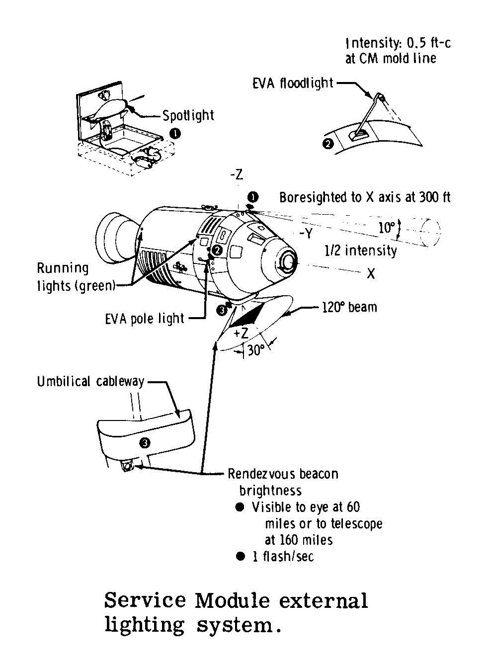
Click image for a 982x1348 pixel version of this image in a new window.
Adapted from page 16 (p. 19 in the PDF) of the Apollo Experience
Report: Crew Station Integration. Volume 5: Lighting
Considerations.
Extraction and adaptation by heroicrelics.
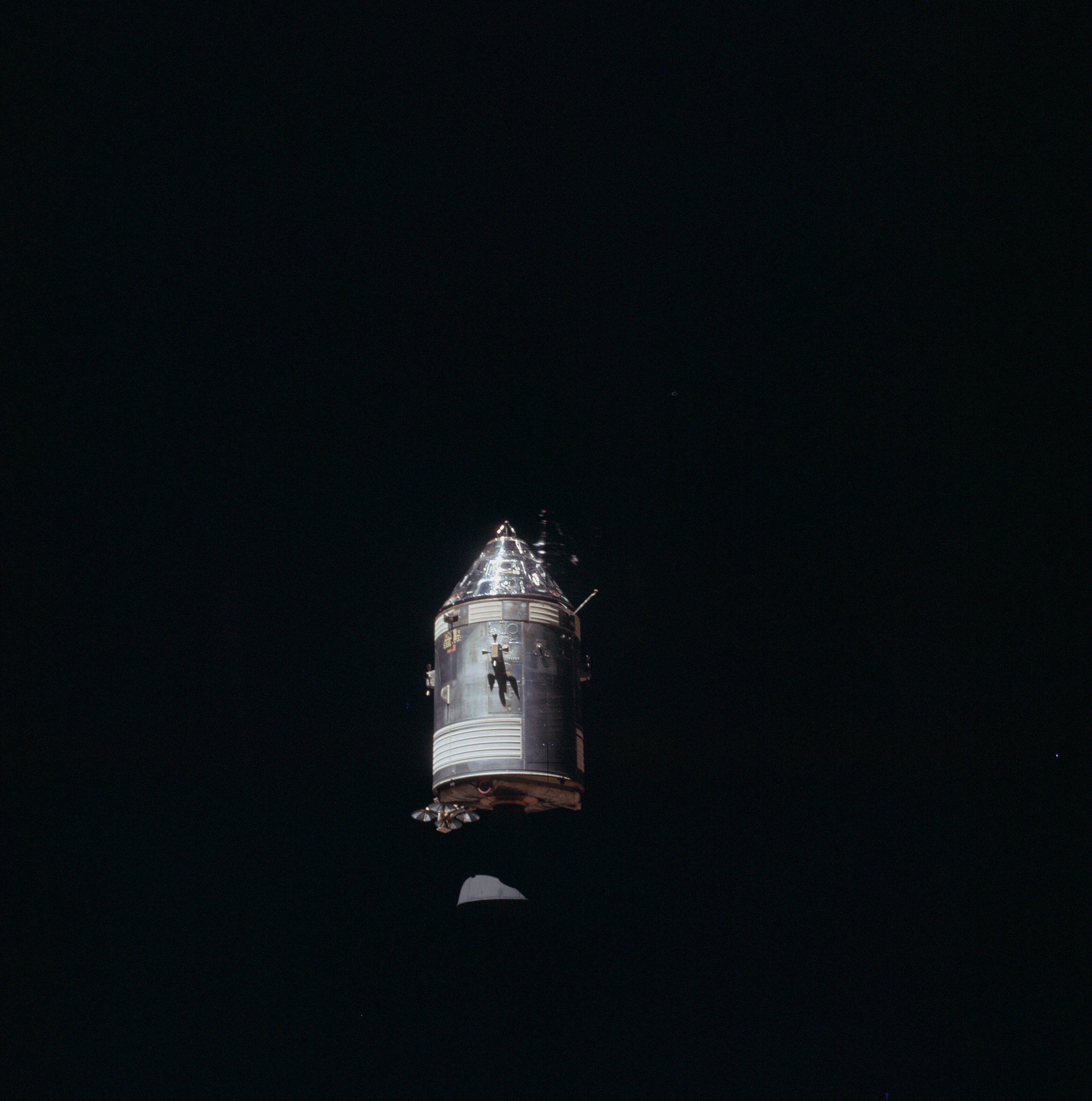
In the composite image below, the EVA floodlight is deployed and visible toward the right of each image's Service Module (on a rod, at approximately a 45° angle). Additionally, the rendezvous spotlight is visible forward of the UNITED STATES decal and aft of the Command Module's roll thrusters. In the top image, the floodlight is stowed and only its door is visible. In the lower image, the floodlight is deployed (door open and hinged on the image's left).
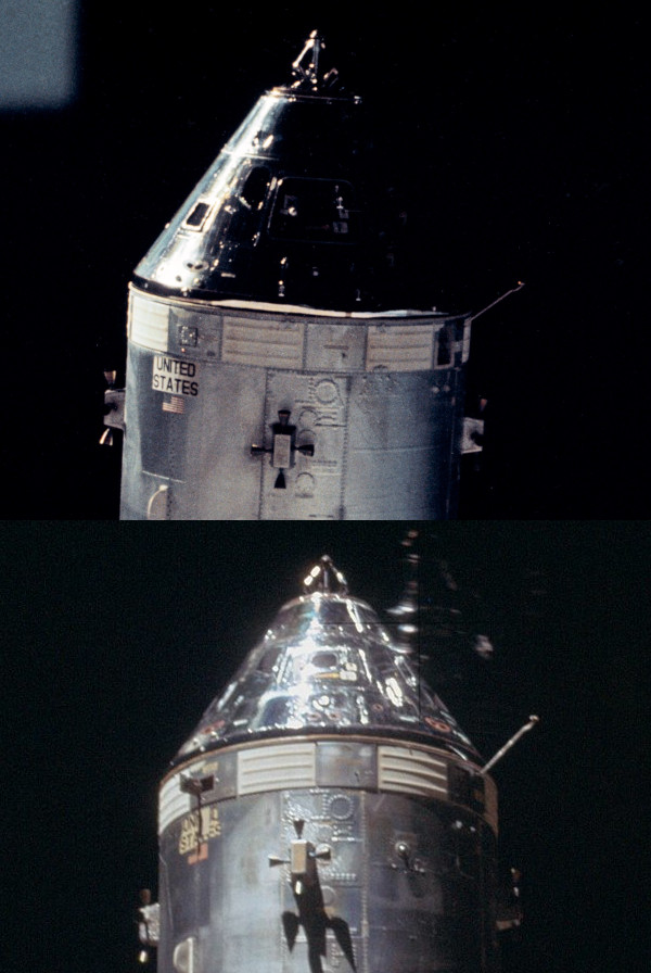
Composite of NASA photos AS09-24-3641 (from
archive.org) and AS14-66-9344
(from the Apollo 14 link of the Project Apollo Archive's
Apollo Image Gallery.
Adaptation by heroicrelics.
The bulk of the descriptive text on this page was taken, largely verbatim, from the Apollo Spacecraft News Reference, the Apollo Experience Report: Crew Station Integration. Volume 5: Lighting, and the Apollo 14 Press Kit.