
Apollo Service Module Service Propulsion System (SPS) Servicing Connections
I've prepared some diagrams of the Apollo Service Module's aft face to accompany my photos of the three remaining Service Modules (CSM-105AV, in the Apollo/Soyuz Test Project (ASTP) display at the National Air & Space Museum; CSM-115A, on the Saturn V at Johnson Space Center (the visitor center for which is Space Center Houston); and CSM-119, in the Apollo/Saturn V Center at Kennedy Space Center.
These diagrams were extracted from a document dated 19 February 1964. Based on the document's date, the diagrams likely depict a Block I Service Module, but I am unaware of any changes in this area of the Service Module in the Block II version.
All three Service Modules are oriented in the same fashion, with the -Z side facing up (the Command Module's hatch facing up). CSM-105AV and CSM-119 are exhibited as stand-alone displays (with nozzle extensions on their Service Propulsion System (SPS) engines), while CSM-115A is displayed, attached to its Spacecraft-Lunar Module Adapter (SLA), with no nozzle extension.
Other than the SPS and its nozzle extension, the aft face of the SM is dominated by the aft heat shield, a mostly-rectangular structure:
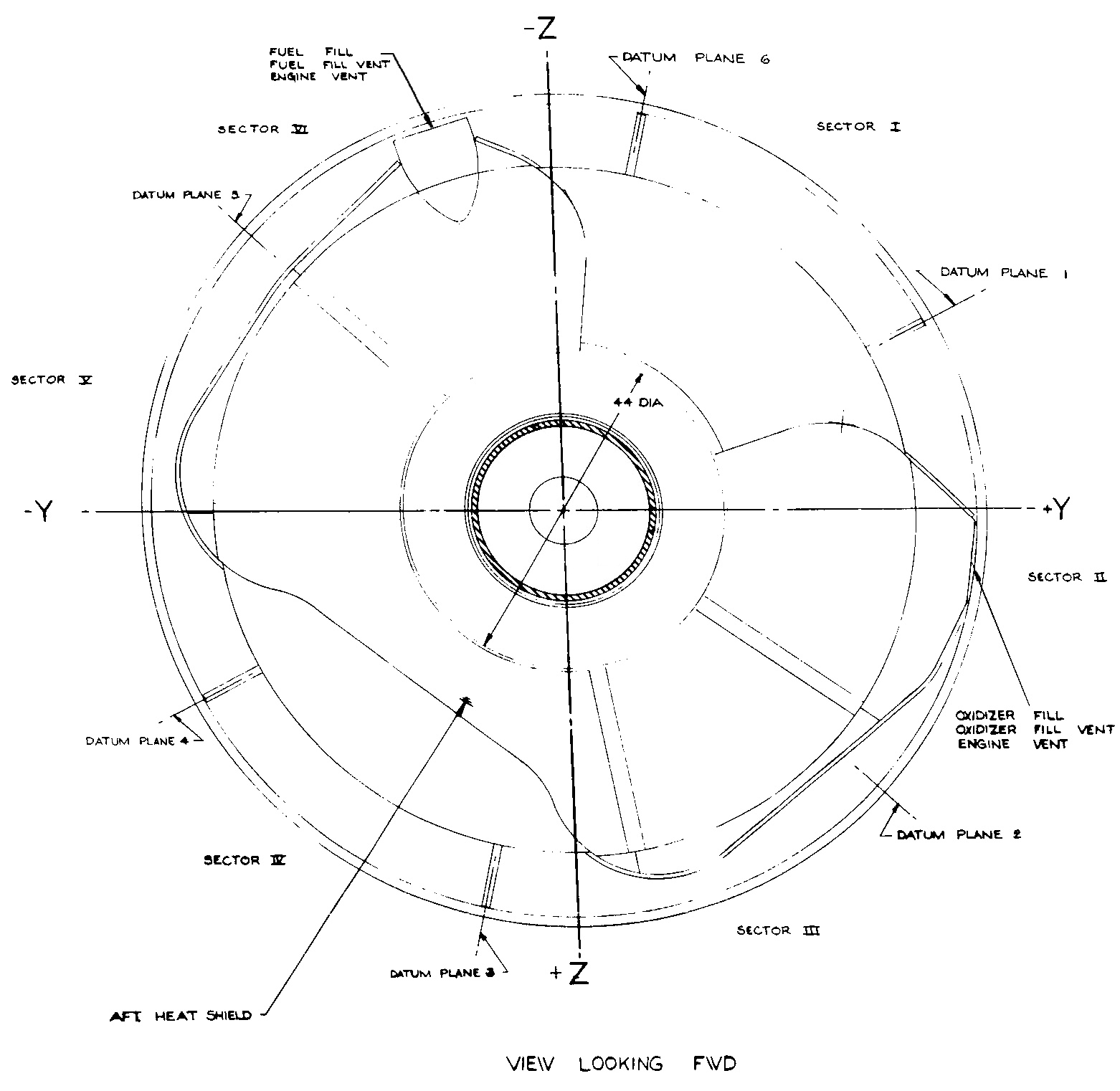
Click image for a 1562x1522 pixel version of this image in a new window.
Adapted from p. 8 (p. 32 in the PDF) of the Apollo
Systems Engineering Manual: Service Module and Adapter
Structure.
Extraction, clean-up, and adaptation by heroicrelics.org.
Propellant fill/drain connectors are located on two corners of the aft heat shield, with the fuel connector on the -Z (top) corner and the oxidizer connector on the +Y (right) corner. The SPS engine used Aerozine 50 (a 50/50 mix of hydrazine and unsymmetrical dimethylhydrazine [UDMH]) and nitrogen tetroxide. These propellants are hypergolic and highly toxic; as such, they were loaded from the Mobile Service Structure, rather than from the Launch Umbilical Tower (LUT), like the launch vehicle.
The next two diagrams remove the aft heat shield and show the plumbing associated with the SPS engine propellant tanks and their fill/drain connectors. These connectors extended aft into the SLA. For a close-up of the oxidizer service connector itself, see dsc08240.jpg on CSM-119.
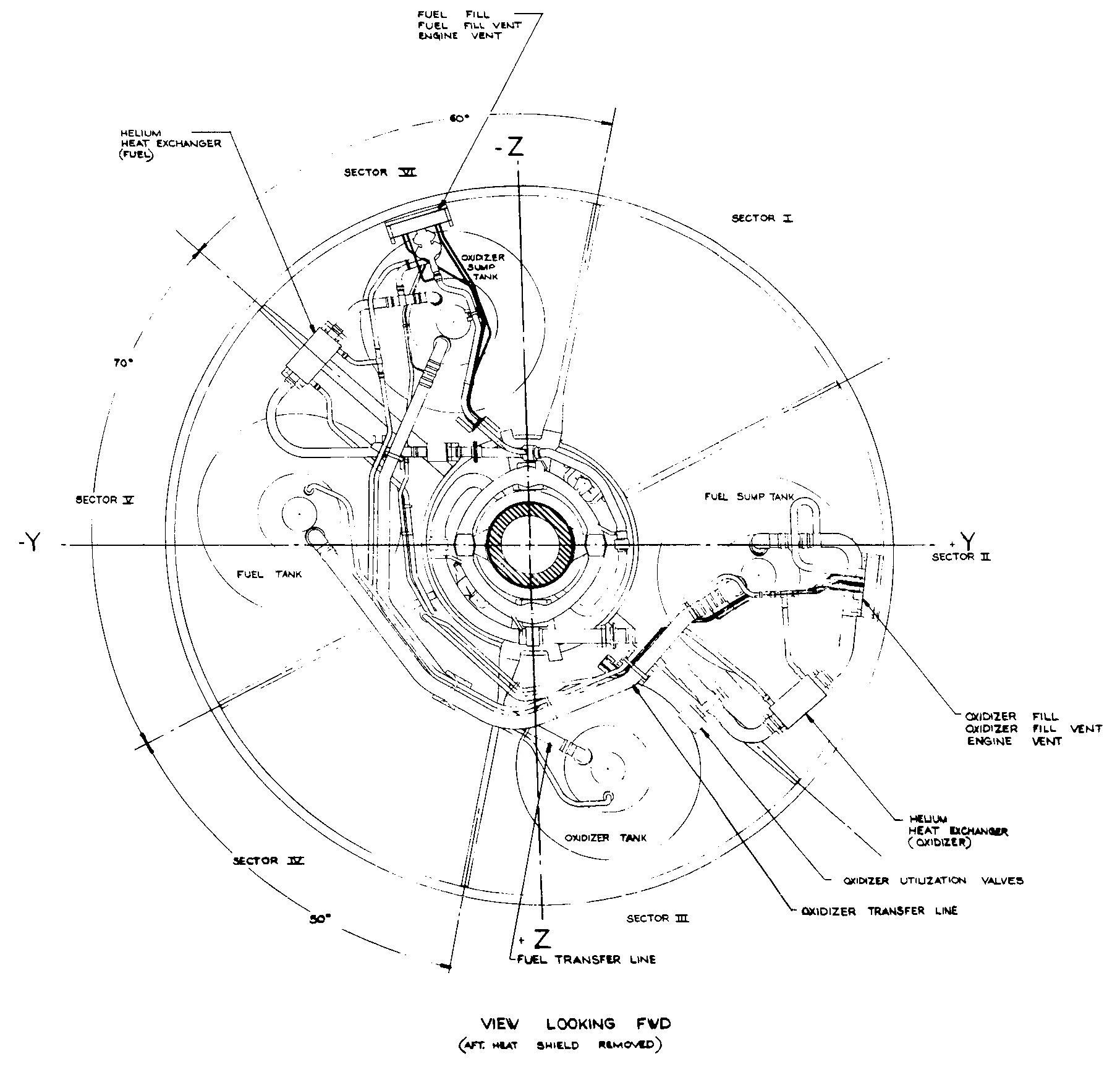
Click image for a 1812x1726 pixel version of this image in a new window.
From p. 8 (p. 32 in the PDF) of the Apollo
Systems Engineering Manual: Service Module and Adapter
Structure.
Extraction and clean-up by heroicrelics.org.
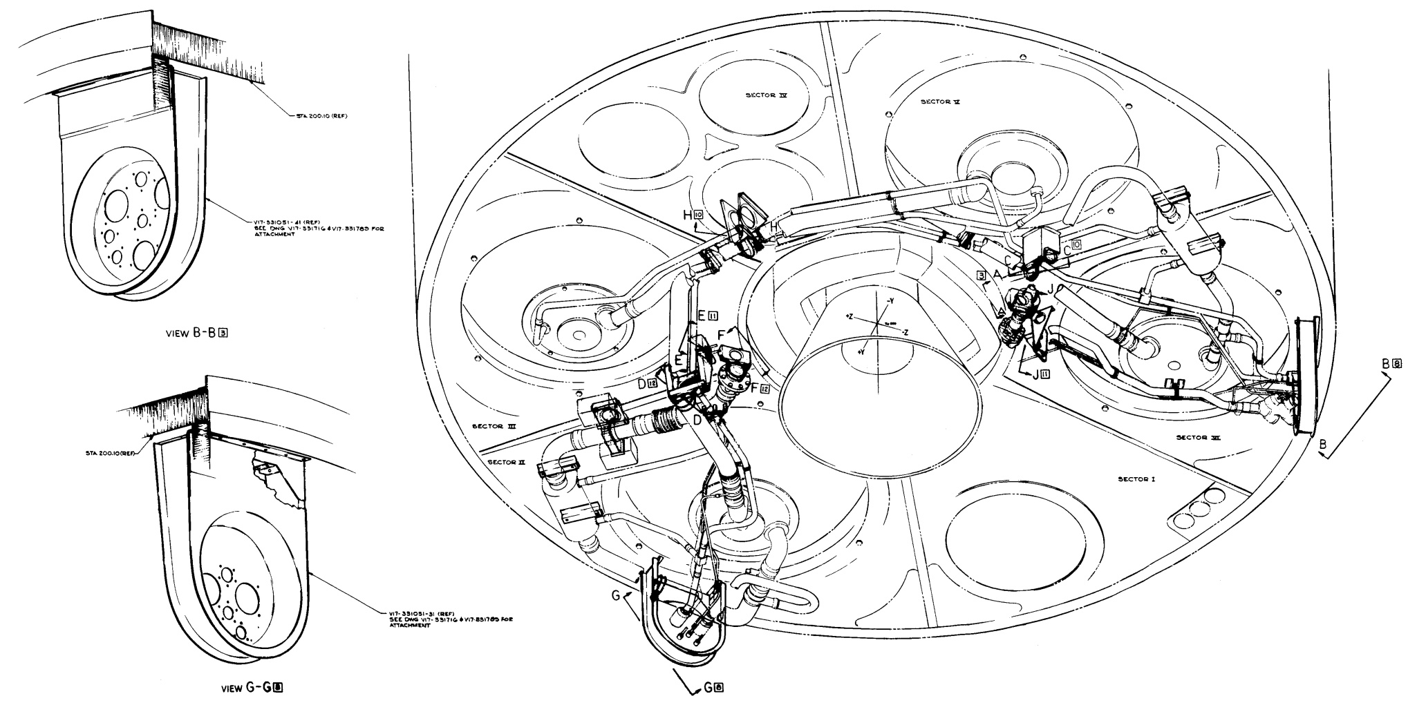
Click image for a 2050x1021 pixel version of this image in a new window, or
click here for a 4556x2268
pixel version of this image in a new window.
Adapted from p. 20 (p. 134 and 135 in the PDF) of the Apollo
Systems Engineering Manual: Service Module and Adapter
Structure.
Extraction, clean-up, and adaptation by heroicrelics.org.
Apollo 7 was unique among the manned Apollo missions in that its SLA panels remained attached to the S-IVB (Saturn V third stage). Upon achieving orbit, the Apollo 7 crew performed a transposition maneuver to simulate docking with a lunar module (no lunar module was carried on Apollo 7).
During this transposition and simulated docking procedure, the crew photographed the S-IVB and the SLA panels. These photos include details of the SPS service connection ports on the SLA panels.
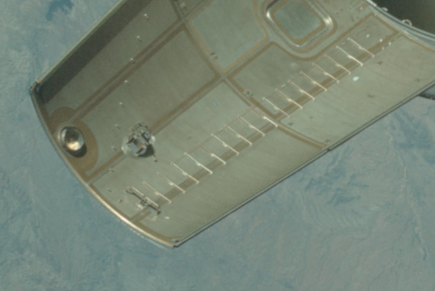
Detail of the oxidizer service connection port. To see how this port mated with the service module, see dsc49565.jpg on my Johnson Space Center Saturn V CSM & SLA photo set at Space Center Houston. As you can see, the cover plate was installed prior to launch after the oxidizer was loaded.
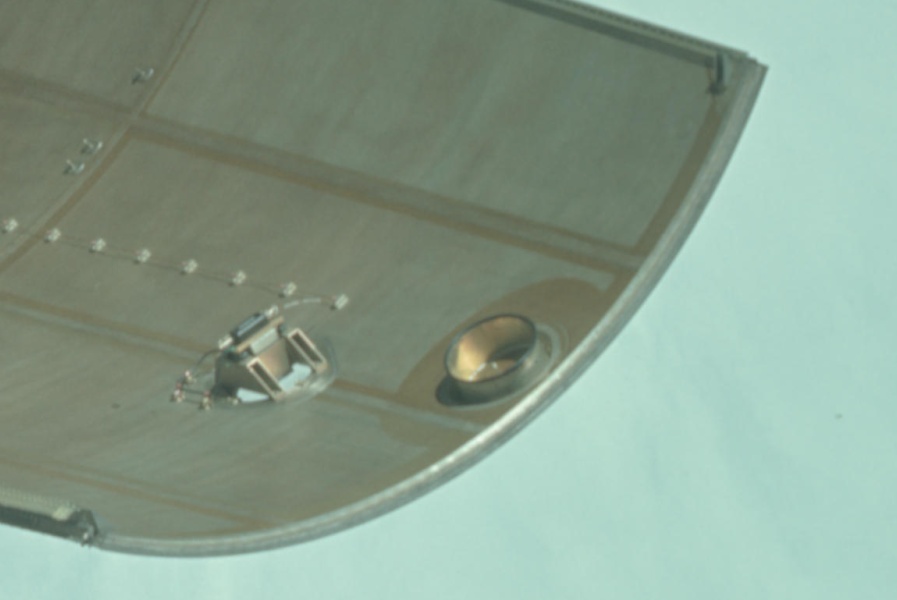
Detail of oxidizer service connection port on SLA panel.
Nearly full-sized crop of photo AS07-3-1539
(courtesy of the Gateway to Astronaut
Photography of Earth).
Detail of the fuel service connection port. To see how this port mated with the service module, see dsc49566.jpg on my Johnson Space Center Saturn V CSM & SLA photo set at Space Center Houston. As you can see, the cover plate (similar to the oxidizer service connection port cover plate) was installed prior to launch after the fuel was loaded.
Detail of fuel service connection port on SLA panel.
Full-sized crop of photo AS07-3-1531
(courtesy of the Gateway to Astronaut
Photography of Earth).