
LR-105 (Atlas Sustainer) Cut-away
The Atlas missile sported three rocket engines, two outer booster (LR-89) engines and one central LR-105 sustainer engine.
The Atlas employed a "stage and a half" concept, with both boosters and the sustainer igniting at lift-off. A bit over two minutes later, the booster engines would shut down and be jettisoned along with the missile boattail, leaving the sustainer engine to propel the missile to its final velocity. (At the time, it was difficult enough to reliably ignite a stationary rocket engine on the ground, much less air-start an engine at velocity.)
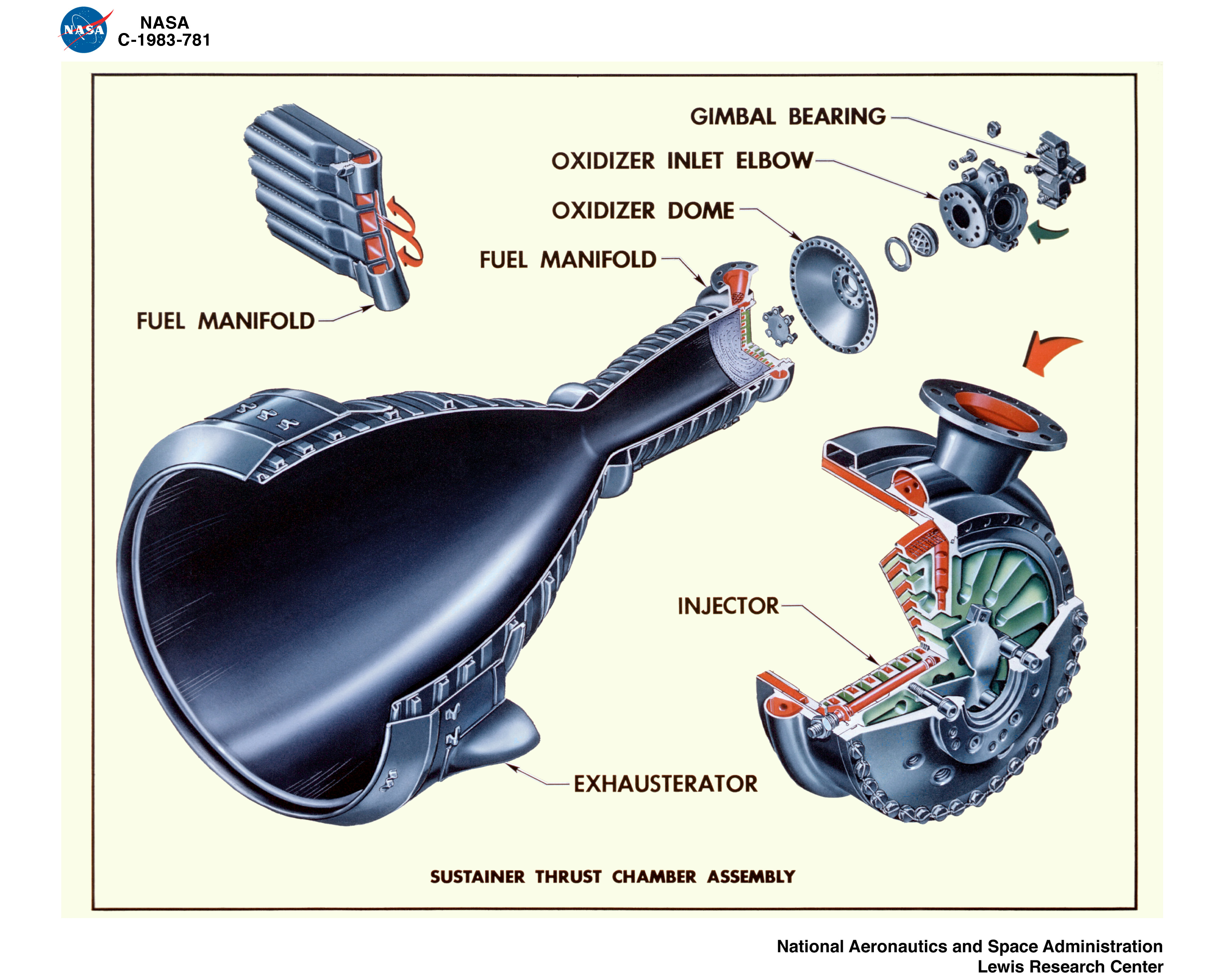
In the same vein as my F-1 thrust chamber and F-1 injector cut-aways, here is a cut-away of an LR-105 Atlas sustainer engine.
Click image for a 3600x2880 pixel version of this image in a new window.
Scan by GRC
ImageNet.
Restoration by heroicrelics.
As is typical of rocket engine diagrams from this era, red signifies fuel flow and green indicates an oxidizer path.
After leaving the turbopump, fuel enters the fuel inlet manifold via the fuel inlet (red arrow at the injector diagram), where it is directed down every other regenerative cooling tube comprising the thrust chamber (the forward end of these tubes are visible near the fuel inlet in the injector cut-away).
The fuel reaches the thrust chamber exit plane, where it enters the fuel return manifold (simply labelled "fuel manifold" in the upper left of the main diagram) and returns to the fuel manifold at the forward end of the thrust chamber via the "up fuel" tubes. The fuel then flows through fuel feed passages (red passage pointing to the 12:00 position in the injector diagram) to the ring grooves comprising the injector, and out the orifices on the injector face.
The liquid oxygen takes a more direct route to the injector, entering the LOX dome via the oxidizer inlet elbow. From there, the LOX is distributed to the ring grooves and then out the orifices on the injector face.
The Atlas' outboard engine's turbine exhaust is dumped overboard via a simple turbine exhaust duct, but for the the LR-105, it is distributed around the periphery of the engine's exit plane via an aspirator (called an "exhausterator" in this diagram; the H-1 rocket engine has a similar aspirator, which was also called an exhausterator by some early Saturn I/H-1 documentation).