
S-IVB (Saturn V) Propellant Tank Pressurization
The S-IVB stage served as both the second stage of the Saturn IB and the third stage of the Saturn V. While essentially the same stage, there were a number of differences in the two versions of the S-IVB due to their different application. One such difference was the method propellant tank pressurization. Not only did the propellant tank pressurization system differ between the the Saturn IB and Saturn V versions of the S-IVB, but the S-IVB pressurization system went through a number of refinements in its Saturn V version.
While the S-IVB's J-2 engine fired, the LOX tank pressure was maintained by "cold helium spheres" located in the LH2 tank: Helium from the spheres was expanded by the J-2's heat exchanger, after which it was routed to the LOX tank. The LH2 tank was pressurized by drawing gaseous hydrogen directly from the engine.
For the Saturn IB version of the S-IVB, this was the only necessary propellant tank pressurization system, as the S-IVB fired only once, placing its playload into orbit. The engine was not reignited and stage's mission was essentially over.
On the Saturn V, however, the S-IVB stage initially burned for a few minutes to place the Apollo spacecraft into Earth orbit. A little over two hours later, the S-IVB's J-2 engine would reignite to perform its trans-lunar injection (TLI) burn, sending the Apollo spacecraft (and usually the S-IVB itself) toward the moon.
During its parking orbit, the S-IVB's fuel tank was allowed to vent; the LH2 tank was routed through a "propulsive vent" which provided a small amount of thrust to keep the propellants settled at the aft end of their respective tanks. However, this meant that the propellant tanks had to be repressurized prior to J-2 reignition for its TLI burn. This repressurization system was unique to the Saturn V version of the S-IVB.
Both the repressurization and the in-flight pressurization systems on the Saturn V version of the S-IVB underwent a number of revisions. Unfortunately, I was able to find no single source documenting these revisions; I had to read many reports about the individual flight stages to obtain this information. My misfortune was compounded by conflicting information in these reports.
On the first two stages (SA-501 and SA-502, on the Apollo 4 and Apollo 6 missions), in-flight pressurization was provided by eight cold helium spheres located in the LH2 tank:
Click image to watch a YouTube video featuring the cold helium spheres in a new
window.
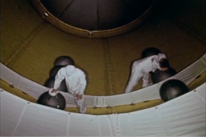
Technicians cleaning S-IVB cold helium spheres
Video capture by heroicrelics
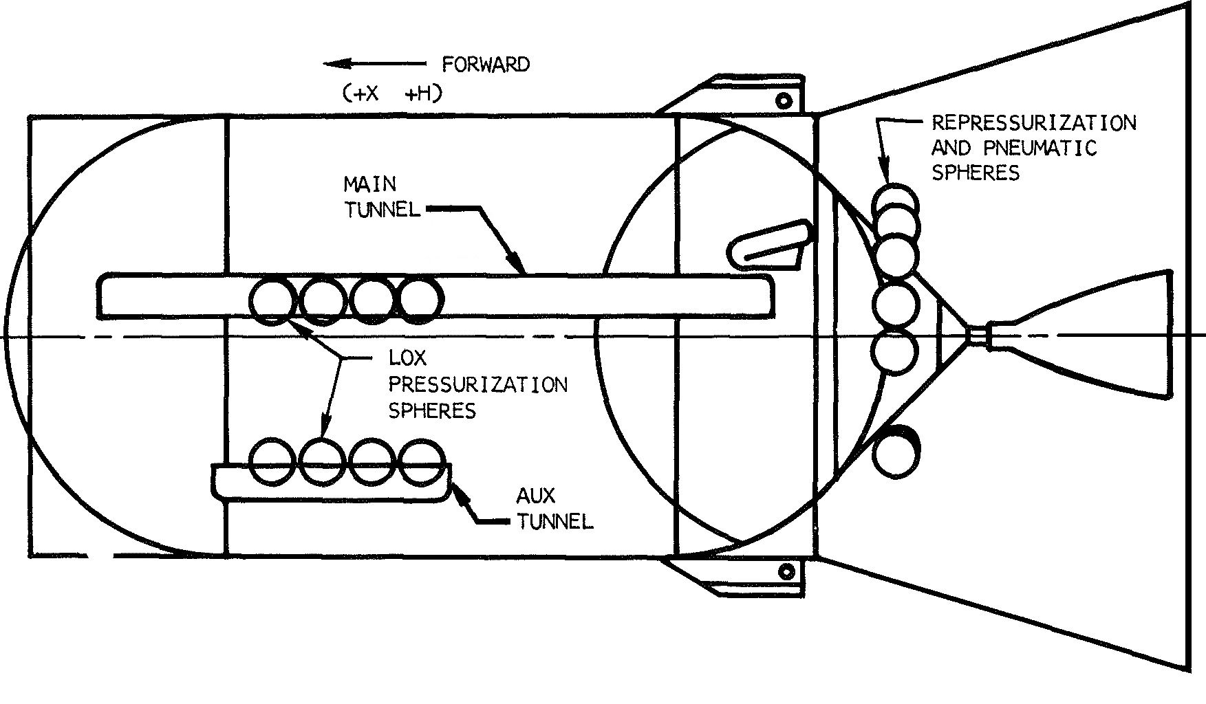
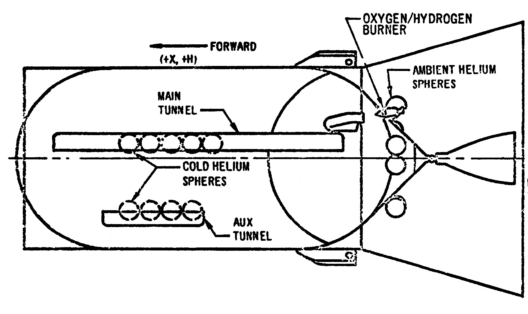
Internally, the cold helium spheres were located along the main and auxiliary tunnels:
Click image for a 1753x1024 pixel version of this image in a new window.
Adapted from p. AP 1-14 (p. 644 in the PDF) of the Saturn S-IVB-502
Stage Flight Evaluation Report
Extraction, clean-up, and adaptation by heroicrelics.
The spheres were connected in series, with spheres 1 through 4 located on the main tunnel and spheres 5 through 8 on the auxiliary tunnel.
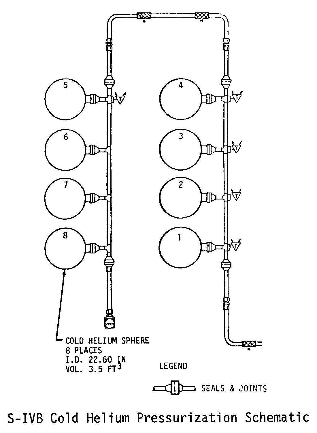
Click image for a 1500x1100 pixel version of this image in a new window.
Adapted from p. 7-49 (p. 195 in the PDF) of the Saturn
V Launch Vehicle Flight Evaluation Report - AS-502 Apollo 6
Mission.
Extraction, clean-up, and adaptation by heroicrelics.
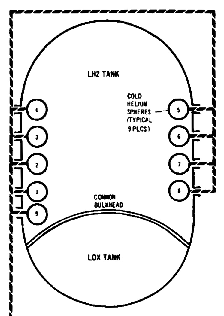
SA-503 (Apollo 8) introduced a new method of repressurizing the propellant tanks, used on all subsequent Saturn V S-IVB stages (discussed below). This new method employed an O2H2 burner (aka "helium heater"), which also drew helium from the cold helium spheres. With this increased demand, a ninth cold helium sphere was added to accommodate this increased helium consumption (no doubt about which sphere was added later; look at the sphere numbering scheme below!):
Click image for a 746x1052 pixel version of this image in a new window.
Adapted from p. 11-17 (p. 303 in the PDF) of the Saturn S-IVB-503N
Stage Flight Evaluation Report
Extraction, clean-up, and adaptation by heroicrelics.
This new, ninth sphere was added along the main tunnel:
Click image for a 1786x1062 pixel version of this image in a new window.
Adapted from p. AP 1-19 (p. 612 in the PDF) of the Saturn S-IVB-503N
Stage Flight Evaluation Report
Extraction, clean-up, and adaptation by heroicrelics.
The Model Specification, Saturn S-IVB-F Stage indicates that the cold helium spheres "will be secured on the [LH2] tank wall at the tunnel so that all plumbing and connections are outside the tank" and that the "auxiliary tunnel connecting the cold helium bottle outlets with the forward skirt area will be designed to accommodate tubing, wiring, and other S-IVB stage requirements." Presumably, spheres 5 through 8 connect to tubing leading up the auxiliary tunnel, across the forward skirt, down the main tunnel (connecting with the remaining four or five spheres), and then down to the thrust structure and the J-2's heat exchanger and the O2H2 burner. (Unfortunately, the Model Specification, Saturn S-IVB-D Stage reveals that each cold helium sphere on that stage is simulated with a "dummy mass", so the pictures I took of S-IVB-D on the U.S. Space & Rocket Center's Saturn V during its restoration don't reveal anything.) And my pictures of the S-IVB-514 forward skirt on Johnson Space Center's Saturn V lack sufficient detail to trace any tubing to or from either the main or auxiliary tunnels.
The addition of the ninth cold helium sphere and the flight stage in which it was introduced (S-IVB-503N on SA-503) was relatively straightforward to determine; however, the propellant tank repressurization scheme took a good deal more research.
The first two Saturn V S-IVB stages repressurized their propellant tanks using helium from "ambient helium spheres", located on the S-IVB's thrust structure. Helium was drawn from these spheres and routed to the propellant tanks to effect the repressurization. There were 10 ambient helium spheres in all, numbered 1 through 10. Spheres number 1 and 2 were used to repressurize the LOX tank. Spheres 3, 5, 6, 7, 8, 9, and 10 were used to repressurize the LH2 tank. Sphere number 4 was used for stage pneumatic control (e.g., operation of valves).
The ambient helium spheres were arranged in groups; there was a group of three, a group of two, and a group of five.
I was able to find only one image of an S-IVB showing the cluster of five ambient helium spheres; the cluster of three pheres is visible, while the J-2 blocks the view of the cluster of two. Adding to the elusive nature of a picture showing the cluster of five spheres, this picture is supposedly dated 01-01-1960; Douglas was not awarded the S-IVB contract until December 21, 1961.
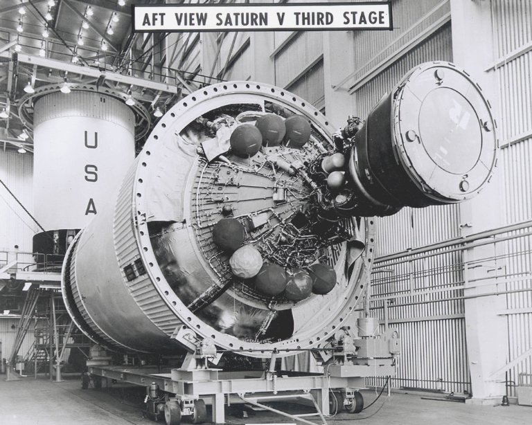
NASA photo MSFC-9903170.
Click image for additional information about this photo at the Internet Archive.
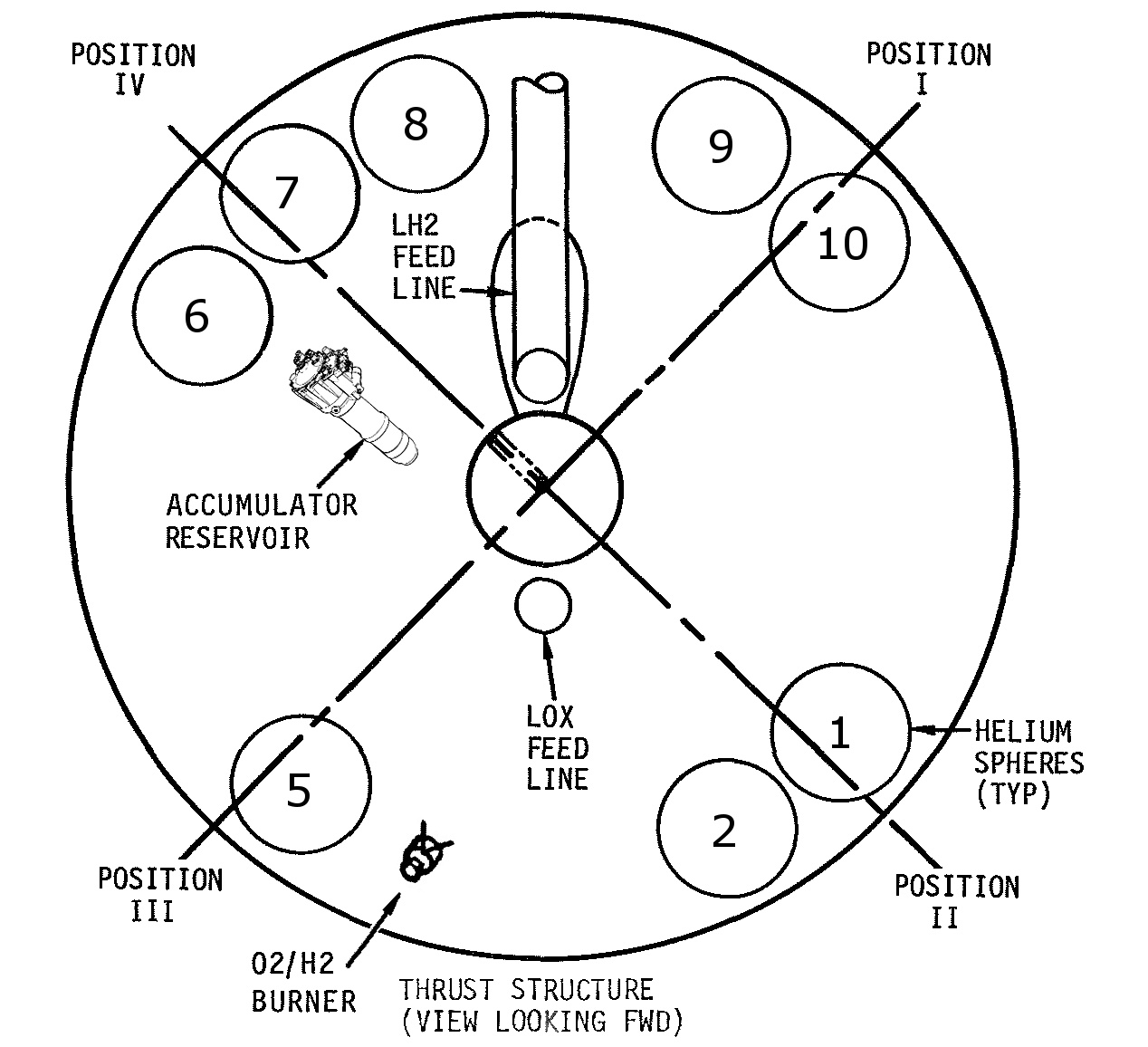
I found a diagram in the Saturn S-IVB-502 Stage Flight Evaluation Report which showed the location of instrumentation on the thrust structure of the S-IVB; it also showed the locations of the ambient helium spheres and the LH2 feed line. I adapted this diagram, removing the instrumentation locations (which cluttered up the diagram). I also added the the flight control system hydraulic fluid accumulator reservoir which, along with LH2 feed line, can help the orient the stage when viewing pictures of it (either the accumulator or the feed line are visible in the majority of the pictures you'll find; the accumulator is clearly visible in the picture above). Finally, I numbered the spheres.

Click image for a 1268x1156 pixel version of this image in a new window.
Figure adapted from p. 26-31 (p. 629 in the PDF) of the Saturn S-IVB-502
Stage Flight Evaluation Report
Extraction, clean-up, and adaptation by heroicrelics.
| Function | Sphere Allocation |
|---|---|
| LOX repress: | 1, 2 |
| LH2 repress: | 3, 5, 6, 7, 8, 9, 10 |
| Stage pneumatic control: | 4 |
The repressurization method employing the O2H2 burner introduced on SA-503 was used on all subsequent Saturn V S-IVB stages. The O2H2 burner was the primary repressurization method, with repressurization via the ambient helium spheres relegated to a backup role. With the reduced reliance on the ambient helium spheres, two where eventually removed; indeed, the O2H2 burner was mounted on the S-IVB's thrust structure in the place formerly occupied by of one of the ambient helium spheres.
The Saturn V Launch Vehicle Flight Evaluation Report - AS-503, Apollo 8 Mission's "S-IVB Significant Configuration Changes" section describes this change as follows:
System Change Reason Propulsion Dual repressurization system using:
- Cryogenic mode for repressurization of both the LOX and LH2 tank using the O2/H2 burner and cold helium
- Ambient mode for repressurization using the ambient repress bottle.
Provide repressurization system redundancy and checkout of cryogenic mode.
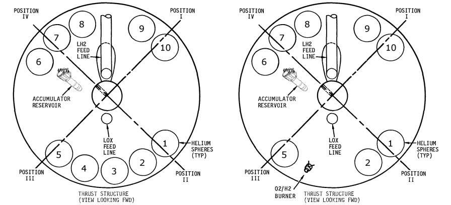
Skipping ahead to the S-IVB's final configuration of ambient helium spheres, introduced on SA-505 (Apollo 10), there were eight ambient helium spheres. Still numbered 1 through 10, spheres number 1 and 2 were still used to repressurize the LOX tank. Spheres 5, 7, 8, 9, and 10 were used to repressurize the LH2 tank (no longer using spheres 3 or 6 from the SA-501/502 configuration for this purpose). Sphere number 6 was now used for stage pneumatic control, replacing sphere number 4 in this role. Rather than renumbering all of the spheres to reflect the two removed spheres, spheres 3 and 4 were simply deleted from the numbering scheme.
The location of the spheres now looked like this:
Click image for a 1268x1156 pixel version of this image in a new window.
Figure adapted from p. 26-31 (p. 629 in the PDF) of the Saturn S-IVB-502
Stage Flight Evaluation Report
Extraction, clean-up, and adaptation by heroicrelics.
| Function | Sphere Allocation |
|---|---|
| LOX repress: | 1, 2 |
| LH2 repress: | 5, 7, 8, 9, 10 |
| Stage pneumatic control: | 6 |
The two remaining Saturn V S-IVB flight stages on display (S-IVB-513 at Johnson Space Center and S-IVB-514 at Kennedy Space Center) share this ambient helium sphere configuration:
| S-IVB-513 (Johnson Space Center) | S-IVB-514 (Kennedy Space Center) | ||
|---|---|---|---|
 dsc49693.jpg |
 dsc49687.jpg |
 dsc05986.jpg |
 dsc05984.jpg |
Click thumbnail to open image's page in a new window.
Returning now the the ambient sphere configuration on SA-503 and SA-504 (Apollo 8 and Apollo 9), each flew with nine ambient helium spheres. Oddly enough, the spheres on these stages were numbered 1, 2, 5, 6, 7, 8, 9, 10, and 11. The spheres' functional allocation was the same as in SA-505 and subsequent (spheres number 1 and 2 for LOX repress; spheres 5, 7, 8, 9, and 10 for fuel repress; and sphere 6 for pneumatic control), with sphere 11 additionally being used for fuel tank repress.
I really can't explain the mysterious appearance of sphere 11. The plan to use the O2H2 burner was long in the works; a memo dated November 10, 1965 -- almost exactly two years prior to the launch of the first Saturn V -- entitled "Differences of Configuration in Successive Saturn IB and Saturn V Vehicles" indicated
Stage Effective
on
VehicleConfiguration Difference Primary Reason For Difference S-IVB SA 503 Add Helium Heater and Delete Excess Helium Bottles Increase propellant settling during coast due to 30 pound continuous thrust from helium heaters. Resulted in a weight reduction (850 lb).
Clearly, a plan was in place to delete "excess helium bottles;" the plural "bottles" was used.
Oddly enough the Narrative End Item Report on Saturn S-IVB-503, the "original" S-IVB for SA-503, prior to S-IVB-503's explosion and the subsequent renaming of S-IVB-504 to S-IVB-503N, contains a "Propulsion System Schematic" (p. 90 of the report; p. 97 in the PDF) illustrating a total of only eight ambient helium spheres, (numbered 1, 2, 5, 6, 7, 8, 9, 10, with sphere allocation identical to S-IVB-505N and subsequent). There's no indication as to why an eight-sphere stage was manufactured, only to have its replacement be a nine-sphere stage.
There was an anomaly on SA-501 which led to the conclusion that the LH2 tank vent did not fully close during fuel tank repressurization; the result was that tank pressure was lower than desired prior to J-2 restart (reference Saturn V Launch Vehicle Flight Evaluation Report - AS-501 Apollo 4 Mission, p. 7-33 [p. 183 in the PDF]). Perhaps this led the engineers to rethink the deletion of two spheres as planned? That is, they did "delete" two spheres, only to add one contingency sphere? Perhaps they called it sphere 11 to emphasize that it was a deviation from the original plan and that its presence was only temporary? SA-504 did feature a third burn of the J-2 engine, with the second tank repressurization being performed by the ambient helium spheres; perhaps they felt they needed to have a sixth ambient sphere to accomplish LH2 tank repress? But why implement this on SA-503? There's no discussion of the deletion or re-addition of ambient helium spheres in any of the Saturn V Launch Vehicle Flight Evaluation Reports for the affected vehicles, so I'm left to speculate.
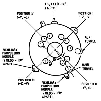
In any case, the physical configuration of the ambient helium spheres now looked like the following; it's essentially the same as the final configuration, above, but with sphere 11 added in a new location. I found this diagram in the Saturn S-IVB-503N Stage Flight Evaluation Report, which showed configuration stations of the S-IVB. I adapted the diagram, rotating it to be in the same orientation as the other diagrams and adding the the flight control system hydraulic fluid accumulator reservoir, as I did above. Finally, I numbered the spheres. Note that the circles made with a dashed line by the main and auxiliary tunnels in this diagram represent the location of the cold helium spheres, inside the LH2 tank.

Click image for a 1197x1206 pixel version of this image in a new window.
Figure adapted from p. AP 1-19 (p. 612 in the PDF) of the Saturn S-IVB-503N
Stage Flight Evaluation Report
Extraction, clean-up, and adaptation by heroicrelics.
| Function | Sphere Allocation |
|---|---|
| LOX repress: | 1, 2 |
| LH2 repress: | 5, 7, 8, 9, 10, 11 |
| Stage pneumatic control: | 6 |
I didn't set out to undertake such an extensive research project; I thought I was going to write a quick little info page on the O2H2 burner. As part of that page, I was simply going to mention the ambient helium spheres. However, I couldn't find a definitive reference indicating the number of ambient spheres; just about each reference I read provided a different number, and I just couldn't leave well enough alone. But at least now there is a definitive reference on ambient helium spheres :-)
Rationale for Sphere Numbering
When I originally created this page, I hadn't seen a diagram or read any document indicating the physical location of any specific sphere number. Based on the available information, I made some logical assumptions and proposed a numbering scheme (which, as it turns out, seems to be correct).
So, what did I consider a "logical assumption"? Well, the spheres (on most stages, at least) were numbered from 1 to 10. Since the physical arrangement of the final 8-sphere configuration looks like the physical arrangement of the original 10-sphere configuration with two spheres (numbers 3 and 4) removed, it seemed pretty straight-forward to propose
Additionally, the Saturn IB version of the S-IVB has only one ambient helium sphere, the pneumatic control sphere; it is located by the accumulator reservoir. On all but the first two of the Saturn V S-IVB stages, sphere 6 was the pneumatic control sphere. It makes sense that placing the pneumatic control sphere in the same location on the Saturn V and Saturn IB versions of the S-IVB would reduce the number of differences between the versions of the stages which would, in turn, make manufacturing and testing of the stages easier. (Of course, the pneumatic control sphere was sphere 4 on the first two Saturn V S-IVB stages; having it in a different location lacks this sense of commonality and may well counter my argument.)
When "sphere 11" was added to the 9-sphere stages (SA-503 and SA-504), it was physically located next to the sphere I decided to call sphere 10, so it made perfect sense to propose
One oddity I did find was a picture on the formercloudster.com's "Sacramento Test Stands" pages: The first image on the second row is supposedly a picture of S-IVB-504 in the foreground, which clearly has eight visible ambient helium spheres in the 8-sphere configuration and lacks the ninth sphere in the location indicated by the diagram. However, by the time that this picture would have been taken, S-IVB-503 would have exploded on the test stand, S-IVB-504 would have been renamed to be S-IVB-503N, and S-IVB-505 would have been renamed to be S-IVB-504N, so no picture of "S-IVB-504" could ever have been taken like this. It could just be that the caption of the picture was simplified (by dropping the "N"s), or it could actually be completely mislabeled. Or it could be that sphere 11 was added to the stage after the test firing. On the other hand, perhaps this info page may not be as definitive as I had hoped ...
Interestingly enough, I tried searching for photos of S-IVB stages being stacked in the VAB, on the assumption that any photos taken of a stage during the manufacturing and testing regime may have represented an earlier, pre-flight configuration but that the sphere configuration would have had to have been frozen by the time it was erected. Unfortunately, I found that pictures of the S-IVB during stacking in the VAB would actually be of little use, as it appears that work platforms were installed in the interstage, obscuring any such view.
Eventually, however, my diligence paid off: While reading the Narrative End Item Report on Saturn S-IVB-505N, I found that it listed a "Ref. Location" of the ambient spheres using locations such as "Pos 8 Str 20". All of the "Pos" numbers corresponded to ambient sphere numbers (1, 2, 5, 6, 7, 8, 9, and 10, in this case), so I assumed that the "Pos" corresponded to the sphere numbers and that "Str" referred to the stringer number.
I asked Alan Lawrie if he had any information regarding S-IVB stringer numbers. He had in his collection a copy of a blueprint of S-IVB-503 (the original S-IVB stage which exploded on January 20, 1967) which was part of a failure investigation report. Not only did it have stringer numbers, but it had ambient helium sphere numbers as well! The blueprint was faded and was drawn from the forward-looking-aft perspective (whereas my diagrams above are all aft-looking-forward), but it confirmed my initial proposed numbering of the eight-sphere configuration:
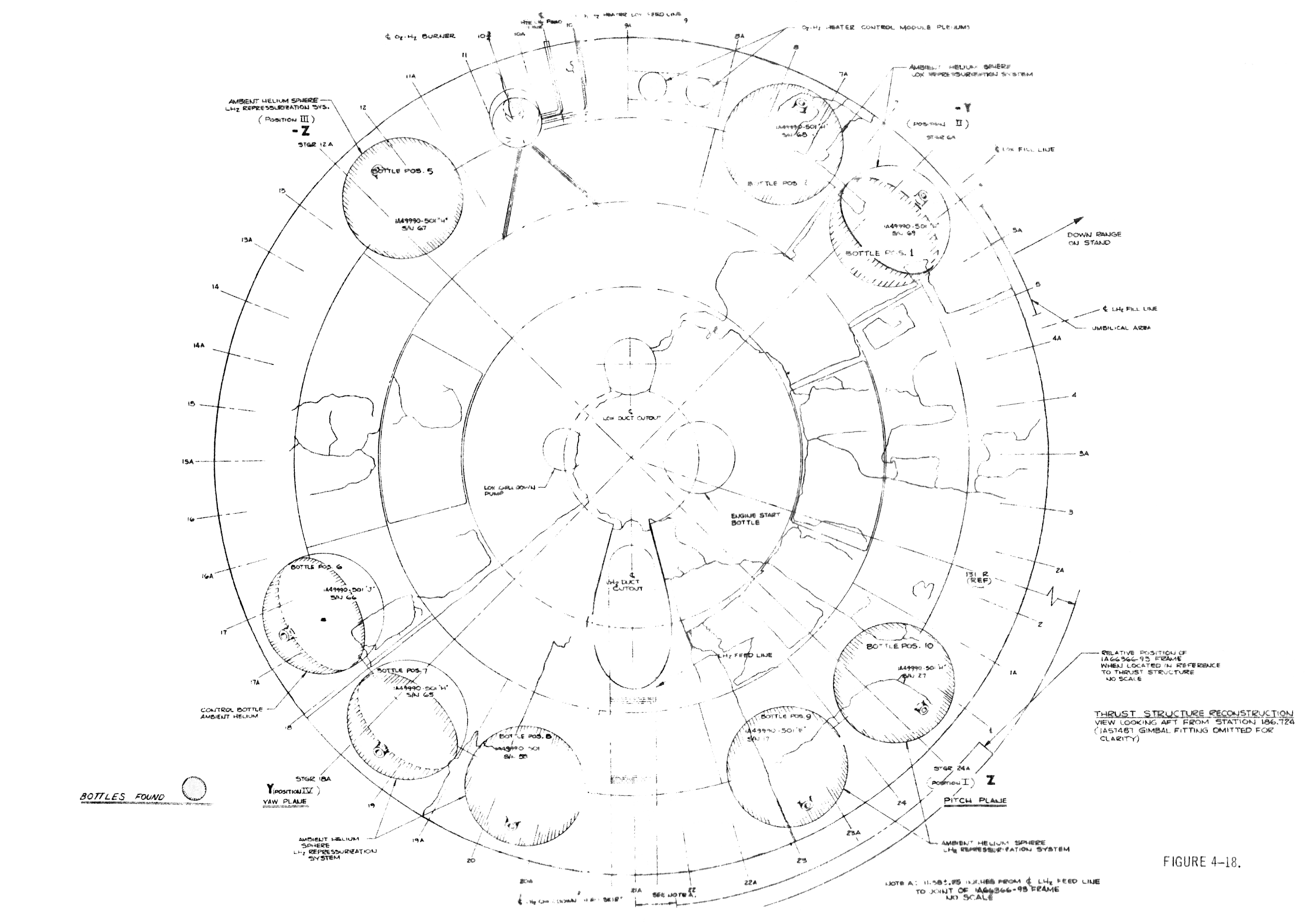
Click image for a 5536x3880 pixel version of this image in a new window.
From the Alan Lawrie collection
Clean-up by heroicrelics.