
General Delta Diagrams
This is a collection of diagrams of the Delta launch vehicle which, while interesting, are not so interesting that they necessarily merit their own separate page. I have created this page as a repository for such diagrams.
Delta Overview
The Delta was a three-stage launch vehicle which first flew for NASA on May 13, 1960. It used a modified Thor missile as its first stage and a modified and improved second stage from the Vanguard and Thor-Able programs. A spin-stabilized, solid-propellant Altair served as its third stage. The first stage used LOX and RP1 as propellants, while the second stage used unsymmetrical dimethylhydrazine (UDMH) and inhibited red fuming nitric acid (IRFNA), although some sources cite inhibited white fuming nitric acid as the oxidizer.
I'm unclear as to when the launch vehicle stopped being called a "Thor-Able" and started being called the "Delta".
There were many variants of the Delta, including the Delta A through the Delta N, which primarily had incremental improvements such as upgrading engines, lengthening propellant tanks, and adding solid rocket boosters around the base of the first stage. Some configurations omitted the third stage. Later, the Delta nomenclature system switched over to a four-digit numbering system describing the specific combination of the variant of the first stage, the number of strap-on solids, and the type of second and third stages.
As the booster evolved, it resembled the original Thor-Able configuration to lesser and lesser degrees, until the Delta II was introduced. Although its first stage was technically called a "Extra-Extended Long Tank Thor", it did not actually resemble the Thor, and by then the second stage had the same diameter as the first stage.
Delta Vehicle for Telstar
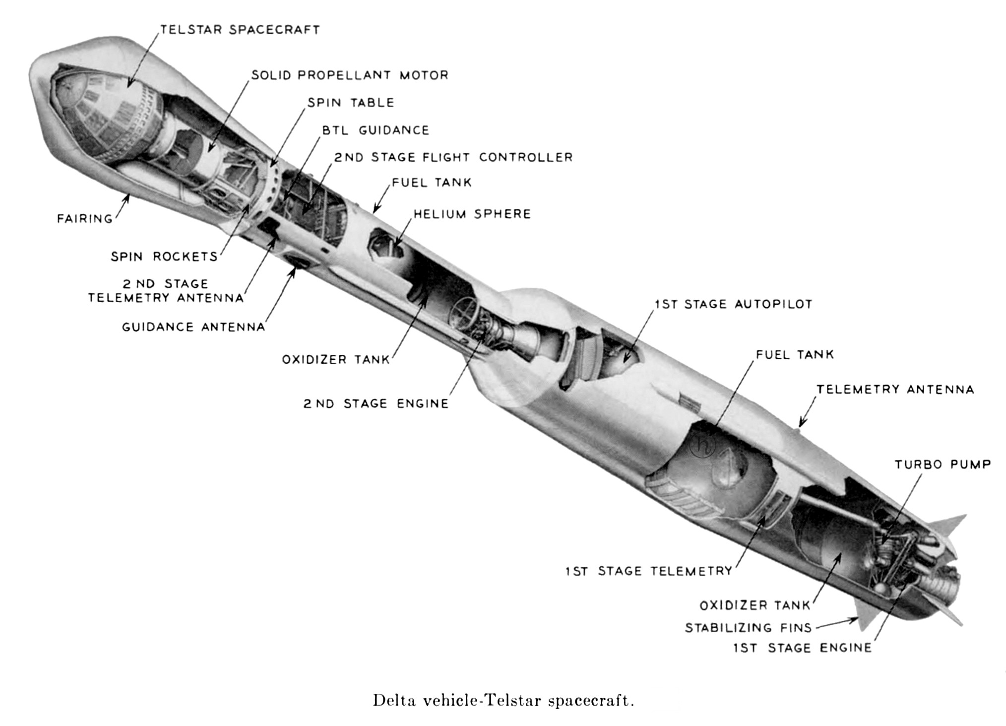
Here is Delta No. 11, an early Delta launch vehicle used to launch the Telstar I satellite:
Click image for a 2028x1463 pixel version of this image in a new window.
From page 1467 (p. 335 in the PDF) of NASA SP-32, Telstar
I, Volume 2, June 1963.
Extraction and cleanup by heroicrelics.
Callouts on this diagram include
- Fairing
- Spin Rockets
- 2nd Stage Telemetry Antenna
- Guidance Antenna
- Oxidizer Tank
- 2nd Stage Engine
- 1st Stage Telemetry
- Oxidizer Tank
- Stabilizing Fins
- 1st Stage Engine
- Telstar Spacecraft
- Solid Propellant Motor
- Spin Table
- BTL [Bell Telphone Laboratories] Guidance
- 2nd Stage Flight Controller
- Fuel Tank
- Helium Sphere
- 1st Stage Autopilot
- Fuel Tank
- Telemetry Antenna
- Turbopump
Telstar 1 was launched from Cape Canaveral on July 10, 1962 from Launch Complex 17B (located fairly far south on Cape Canaveral, not in numerical order, and just north of Launch Complex 5/6).
As per NASA SP-32, Telstar I, Volume 2, June 1963, Delta No. 11 was a three-stage rocket with ground-guided, liquid-fueled first and second stages and a spin-stabilized, solid propellant third stage. A bulbous fiberglass fairing surrounded the third stage and Telstar spacecraft mounted on it. The launch vehicle was approximately 90 feet high and weighed about 57 tons, fueled and ready for launch.
The first stage was an operational-type Thor missile modified for Delta use. Its engine used RP-l (kerosene) fuel with liquid oxygen (LOX) as the oxidizer. A flight controller employing three integrating gyro, three rate gyros, and a programmer was used to provide open-loop control until the ground guidance system took control about 90 seconds after lift-off. Control was maintained by a combination of the gimballed main engine nozzle and two small vernier engines.
The second stage's propulsion system used unsymmetrical dimethylhydrazine fuel (UDMH) and inhibited white fuming nitric acid as the oxidizer. A gaseous nitrogen retro system was used on the second stage to provide reverse thrust to get the required separation distance between the second and third stages at third stage ignition.
Second-stage in-flight steering control was achieved by hydraulic gimballing of the second stage engine thrust chamber. Roll control was accomplished by discharging helium gas through four roll jets, two of which reacted in a clockwise direction, and two in a counterclockwise direction. Both pitch and yaw control systems responded to commands from the Bell Telephone Laboratories guidance system (Bell Laboratories provided radio guidance systems for all Delta launches of the era).
During the coast period, starting at second-stage burnout and ending at second/third stage separation, the vehicle was turned to its proper spatial orientation by means of a second-stage coast phase control system. The gyros used to control the second stage during the powered portion of flight supplied the attitude reference used to control the gas jet system during the coast phase. An on-off type of gas jet operation was used.
To provide range safety destruct capability, the Delta vehicle carried radio receivers in the first and second stages. The flight termination system in each stage consisted of the receiver and decoder, antenna system, safety and arming mechanism, detonating cord strand to rupture propellant tanks, and a power supply independent of vehicle power. Prior to first/second-stage separation, either system would destroy both stages.
A large-diameter (approximately 22 inches) ball bearing mounted at the forward end of the second stage supported the spin table, which in turn supported the third stage motor and spacecraft. Prior to third stage ignition, the third stage and spacecraft were spin stabilized at approximately 180 rpm by small rocket motors attached to the spin table. The third stage propulsion system had a solid propellant motor.
The separation of the third stage was delayed approximately 2 minutes after nominal fuel depletion to allow time for afterburning and outgassing of the third stage motor and thus prevent contamination of the satellite. The third stage motor was tumbled by an asymmetrical weight after separation to prevent impact with the satellite.
A bulbous fairing was provided to decrease aerodynamic drag and to protect the spacecraft and third stage motor from aerodynamic heating during flight through the atmosphere. This fairing was jettisoned at an altitude of 5 nautical miles, where protection from aerodynamic heating was no longer required.