Return to Goddard Space Flight Center Site Index
Delta Payload Fairing/Shroud
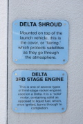
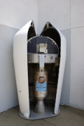
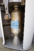
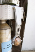
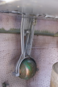
The visitor center also displays a payload fairing typical of those used on the Delta rocket. The payload fairing enclosed both the actual payload and the solid-propellant third stage. At the time, the payload fairing was commonly referred to as the "shroud". Goddard's Rocket Garden page identifies this as actual flight hardware, rather than a mockup.
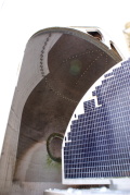
The payload depicted here appears to be an Orbiting Solar Observatory (OSO). The OSO satellite was divided into two parts, a lower, spinning "wheel" and an upper, stationary "sail".
The wheel was constructed of aluminum alloy and was separated into nine wedge-shaped compartments. Five of these compartments contained experiments not requiring solar orientation. The remaining four compartments housed the electronic controls, batteries, telemetry equipment, and radio-command equipment. Each wheel compartment provided approximately 1000 cubic inches of volume, and each wheel experiment could weigh up to approximately 45 pounds. A single experiment could also consume two compartments and weigh up to 90 pounds. The wheel also contains three extendable arms which were folded down around the third stage of the launch vehicle during the launch phase. When the spacecraft was injected into orbit, the arms were extended to increase the effective diameter of the wheel from 44 inches to 96 inches.
The fan-shaped sail was mounted on top of the wheel by means of a rotating aluminum shaft and carried a solar array and pointed experiments. The solar array supplied the electrical power required for daylight operation, and it charged storage batteries for night-time operation. Space was provided in the sail section for two pointed experiments, each 4 inches wide by 8 inches high. The sail section could accommodate a total instrument weight of approximately 88 pounds.
The wheel and sail were connected by an aluminum shaft running from the base of the sail, through the center of the wheel, and terminating in a support ring structure on the underside of the wheel. This shaft is held in place by two bearings, one on top and one on the bottom of the wheel. A torque motor, mounted on the top of the shaft, controlled the azimuth position of the sail while the spacecraft was in daylight. The base of the shaft had a slip-ring assembly which allowed the transmission of power, telemetry signals, and control signals between the sail section and the wheel.
The inherent stability of the spacecraft was due to the gyroscopic spinning of the entire wheel structure. After second stage burnout during the launch phase, the entire third stage and spacecraft combination was spun up to approximately 120 rpm to provide stability for the third stage. Ninety seconds after third-stage burnout, squibs were fired to release the three arms. Centrifugal force extended them, increasing the gyroscopic stability of the wheel and decreasing the spin rate to approximately 96 rpm.
At the end of each arm was a high pressure nitrogen gas tank which supplied nitrogen gas to spin/de-spin jets located on each arm. The wheel rotation was initially reduced by expelling nitrogen gas from the de-spin jets, slowing the wheel to 30 ± 5% rpm. Photoelectric solar sensors (solar eyes) mounted on the rim of the wheel sensed the sun during each revolution. When the measured rotational period dropped below 28.5 rpm, nitrogen gas was expelled from the spin-up gas jets and the spin rate was increased to within 5% of nominal.
Goddard has a page regarding the Orbiting Solar Observatory Series which includes an overview of the entire program plus has pages on each of the eight OSO satellites (it looks like the first six OSOs were of this general construction with OSO-7 and OSO-8 each have a substantially different construction and appearance than the others in the series).
 dsc35436.jpg |
 dsc35441.jpg |
 dsc35448.jpg |
 dsc35442.jpg |
 dsc35440.jpg |
 dsc35443.jpg |
 dsc35444.jpg |