| Prev |
heroicrelics.org Air Force Museum Site Index Cutaway V-2 Engine Combustion Chamber Gallery |
Next |
dsca3659.jpg
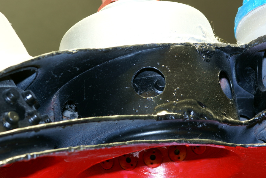
Detail of the inner wall of a burner cup. This particular burner cup is in the inner ring.
This burner cup has some sort of perforated shroud around it; this is presumably to even out the flow of fuel from the main fuel valve. I've personally seen two cutaway V-2 combustion chambers and have seen photos of at least two others. In all of them, only the inner ring of burner cups have these perforated shrouds. However, I'm not certain whether the outer ring lacked shrouds or if all of the combustion chambers were prepared for display in the same fashion, removing the shrouds from the outer ring of burner cups.
Through the holes in the shroud it is possible to see some of the fuel injection nozzles embedded in the burner cup wall.
This photo also shows the three walls of the forward end of the combustion chamber. The "lower head chamber," or lower fuel manifold, is the space between the two aft walls and is part of the normal double-walled combustion chamber construction. At center of the forward end of the combustion chamber would be the main fuel valve. Once the valve opened, it admitted fuel to the "upper head chamber," or primary fuel manifold, where it was allowed to flow between the two walls of the burner cups and through the fuel injection nozzles. The fuel mixed with the atomized oxygen in the burner cup and entered the combustion chamber proper.
| Time picture taken | Wed May 21 12:37:52 2014 |
| Location picture taken |
Missile/Space Gallery Air Force Museum Dayton, OH |
| Prev | Cutaway V-2 Engine Combustion Chamber Gallery | Next |