| Prev |
heroicrelics.org Air Force Museum Site Index Cutaway V-2 Engine Combustion Chamber Gallery |
Next |
dsca3658.jpg
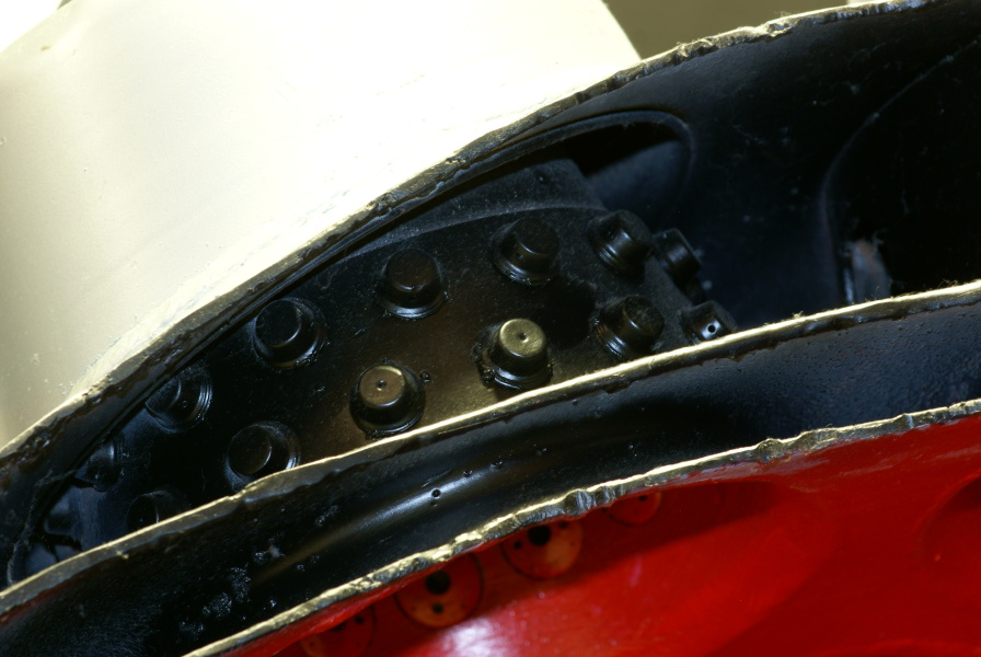
Detail of the inner wall of a burner cup; the space between the outer and inner walls is visible towards the upper portion of this photo. This particular burner cup is in the outer row.
Note the two rows of fuel injection nozzles.
This photo also shows the three walls of the forward end of the combustion chamber. The "lower head chamber," or lower fuel manifold, is the space between the two aft walls and is part of the normal double-walled combustion chamber construction. At center of the forward end of the combustion chamber would be the main fuel valve. Once the valve opened, it admitted fuel to the "upper head chamber," or primary fuel manifold, which is formed by the two forward walls. In the upper head chamber it was allowed to flow between the two walls of the burner cups and through the fuel injection nozzles. The fuel mixed with the atomized oxygen in the burner cup and entered the combustion chamber proper.
| Time picture taken | Wed May 21 12:36:26 2014 |
| Location picture taken |
Missile/Space Gallery Air Force Museum Dayton, OH |
| Prev | Cutaway V-2 Engine Combustion Chamber Gallery | Next |