| Prev |
heroicrelics.org U.S. Space & Rocket Center Site Index Skylab Mockup Gallery |
Next |
dsc18230.jpg
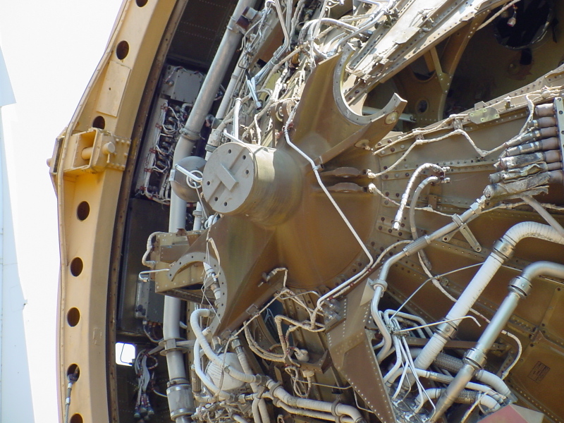
Detail of the aft end of the thrust structure.
Picture 1 of 2.
At center is the stage's J-2 engine gimbal fitting (where the engine's gimbal block would attach to the thrust structure).
On either side of the gimbal fitting (at the 2:00 and 8:00 positions) are the fittings for stage's LOX and LH2feed lines. At upper right is the opening in the thrust structure through which the liquid hydrogen feed line would emerge.
Note the lines at right leading to the panel at lower center; this panel is the stage's "customer connect fluid system," the pneumatic interface to the engine.
Also note, just below the cut-out for the LH2 feed line, are some cut cables from the engine's "customer connect electrical system," the electrical interface to the stage.
| Time picture taken | Sat Jul 15 11:09:51 2006 |
| Location picture taken |
Rocket Park U.S. Space & Rocket Center Huntsville, AL |
| Prev |
heroicrelics.org U.S. Space & Rocket Center Site Index Skylab Mockup Gallery |
Next |